2 2 S D G 7 0 0 0 A Q u i c k S t a r t
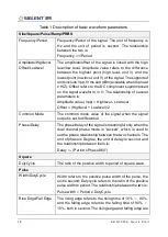
Table 3 I/Q waveform parameter description
Carrier
The frequency of the carrier. When the center frequency =
0, the output is baseband I / Q signal; When the center
frequency ≠ 0, the output is the quadrature modulated IF
signal.
Amplitude
When the center frequency = 0, the amplitude value is the
modulus of the I / Q signal; When the center frequency ≠
0, the signal is only output from channel I, and the
amplitude value is the root mean square value of channel I
output.
Fsymb/Fs
The symbol rate (Fsymb) and sample rate (Fs) are
converted according to the parameter oversampling point
(Pts/Symbol), and the conversion relationship Fs = Fsymb
* (Pts/Symbol). Waveform oversampling point information
can be obtained in "waveform information".
Waveform
Information
The waveform information contains the modulation
parameters of the waveform, including modulation type,
symbol length, oversampling rate, filter type and roll off
coefficient of the filter. It is read-only.
Trigger Source
Internal, External and Manual trigger sources.
Data Source
You can choose to load the built-in waveform or the saved
waveform.
I/Q Adjustment
In baseband I/Q mode, SDG7000A provides the option of
I/Q compensation to minimize the image caused by the
imbalance of the two channels. I/Q compensation options
include gain balance, I-channel offset, Q-channel offset
and Q-angle adjustment.
Summary of Contents for SDG7000A Series
Page 1: ...SDG7000A Arbitrary Waveform Generator EN01A Quick Start...
Page 2: ......

