background image


SDG7000A  Qui ck  Start                                                                                                                                      1 

General Safety Summary 

Carefully read the following safety precautions to avoid person injury and prevent 
damage  to  the  instrument  and  any  products  connected  to  it.  To  avoid  potential 
hazards, please use the instrument as specified. 


To Avoid Fire or Personal Injure. 


Use The Proper Power Line. 

Use only the special power line approved by the state and local authorities. 


Ground the Instrument. 

The instrument grounds through the protective terra conductor of the power line. To 
avoid electric shock, the ground conductor must be connected to the earth. Make 
sure  the  instrument  is  grounded  correctly  before  connecting  its  input  or  output 
terminals. 


Connect the Signal Wire Correctly. 

The potential of the signal wire is equal to the earth, so do not connect the signal 
wire to a high voltage. Do not touch the exposed contacts or components.   


Look over All Terminals Ratings. 

To avoid fire or electric shock, please look over all ratings and signed instructions of 
the instrument. Before connecting the instrument, please read the manual carefully 
to gain more information about the ratings. 


Equipment Maintenance and Service. 

In  the  event  of  an  equipment  failure,  please  do  not  dismantle  the  machine  for 

maintenance. The equipment contains capacitors, power supply, transformers and 

other energy storage devices which may cause high voltage damage. The internal 

devices  of  the  equipment  are  sensitive  to  static  electricity  and  direct  contact  can 

Summary of Contents for SDG7000A Series

Page 1: ...SDG7000A Arbitrary Waveform Generator EN01A Quick Start...

Page 2: ......

Page 3: ...o modify or change parts of or all the specifications or pricing policies at company s sole decision Information in this publication replaces all previously corresponding material Any way of copying e...

Page 4: ...RATION I GENERAL SAFETY SUMMARY 1 SAFETY TERMS AND SYMBOLS 3 MAINTENANCE AND CLEANING 4 FIRST STEPS 5 PREPARATION BEFORE USE 6 THE FRONT PANEL 8 THE REAR PANEL 9 TOUCH SCREEN DISPLAY 10 FRONT PANEL OP...

Page 5: ...onnecting its input or output terminals Connect the Signal Wire Correctly The potential of the signal wire is equal to the earth so do not connect the signal wire to a high voltage Do not touch the ex...

Page 6: ...be in an abnormal state You need to view the specific prompt information You can try to restart the setting If the fault information is still in place do not use it for testing Contact the manufactur...

Page 7: ...to be changed or replaced other than authorized by the manufacturer or agent Safety Terms and Symbols Terms used on the instrument DANGER Indicates an injury or hazard that may immediately happen WARN...

Page 8: ...onnector When cleaning the LCD be careful not to scratch the transparent protective film 2 Use a soft cloth soaked with water to clean the instrument Please disconnect the power supply For more thorou...

Page 9: ...ible for any defect damage or failure caused by any of the following a Attempted repairs or installations by personnel other than SIGLENT b Connection to incompatible devices incorrect connection c Fo...

Page 10: ...nds to tilt the instrument upwards for stable placement as well as easier operation and observation of the instrument Before adjustment After adjustment Connecting to Power Supply The standard power s...

Page 11: ...to Power on Power off Press and hold the power button on the front panel for two seconds to turn off the device or turn it off through the following steps Utility Shut Down The Power button does not d...

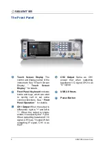
Page 12: ...band I Q signal CH2 is as Q signal Front Panel Keyboard Includes knobs and keys which are used to quickly call or set some common functions See Front Panel Operation for details USB 2 0 Hosts Power Bu...

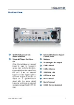
Page 13: ...urst and other functions trigger signal can be output from this port When an external trigger is used a trigger signal is input from the port It can also be output as a synchronization signal with the...

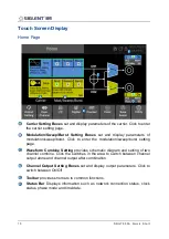
Page 14: ...the modulation sweep burst setting page Waveform Combine Setting provides schematic diagram and setting of two channel combine Click the switches in the area to switch between channel output alone and...

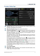
Page 15: ...be displayed Click the parameter value area to set the value through the virtual keyboard or front panel keyboard If the parameter value or unit is followed by an icon it means that there are multiple...

Page 16: ...he clock source The clock source is external but no valid external clock was detected Click this icon to quickly set the clock source The phase mode is Locked Click this icon to quickly set the phase...

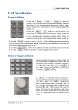
Page 17: ...igital bus is turned on the corresponding button light is on Press the Waveform button to quickly recall the waveform selection menu Press the Utility button to quickly recall the system setup menu Nu...

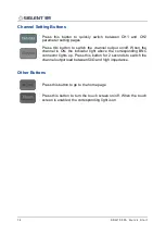
Page 18: ...channel output on off When the channel is ON the indicator light above the corresponding BNC connector lights up Press this button for 2 seconds to switch the channel output load between 50 and high i...

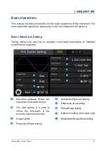
Page 19: ...aking setting sine wave as an example some basic parameters of standard waveform are explained Waveform selection Where you can select the waveform type Amplitude High level setting Offset Low level s...

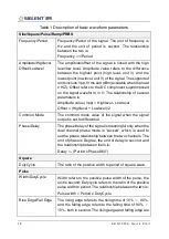
Page 20: ...e value Vpp Highlevel Lowlevel Offset Highlevel Lowlevel 2 Common Mode The common mode value of the signal when the signal output is set to differential Phase Delay The phase delay of the signal is me...

Page 21: ...et 3dB bandwidth of noise adjustable PRBS Bit Rate Period Bit rate Symbol period of PRBS sequence The unit of bit rate is bps and the unit of symbol period UI is second The relationship between the tw...

Page 22: ...S t a r t Arbitrary Waveform Setting Waveform Preview Sample Rate Frequency setting Amplitude Setting Working Mode setting Waveform data source selection Interpolation Mode setting Sequence setting M...

Page 23: ...he basic waveform parameter setting is the same as that of sine wave In AWG mode the signal generator adopts TrueArb technology to output the specified waveform sequence point by point according to th...

Page 24: ...bitrary waveform and its source can come from built in waveform saved waveform or EasyWaveX the number of repetitions of each segment can be set In addition the sequence editor also provides some adva...

Page 25: ...he software EasyIQ on the host computer which is connected with the instrument through USB or LAN In I Q mode CH1 is used as I channel output and CH2 is used as Q channel output The two outputs share...

Page 26: ...ter oversampling point Pts Symbol and the conversion relationship Fs Fsymb Pts Symbol Waveform oversampling point information can be obtained in waveform information Waveform Information The waveform...

Page 27: ...function and open its parameter setting page Modulation type selection Click the modulation type parameter area on the right to select the modulation type Modulation source selection Select the modula...

Page 28: ...eter setting page Sweep type setting Return to the Home Page Trigger source selection Table 4 Sweep type Sweep type Description Linear Its frequency changes linearly from the starting frequency to the...

Page 29: ...tting Burst type setting Trigger source selection Burst parameter setting area Quickly switch to carrier parameter setting page Return to the Home Page Table 5 Burst type Burst type Description NCycle...

Page 30: ...translation requires a special chip the kit needs external USB power supply The kit providing LVDS output directly leads out the LVDS signals without external power supply required Click digital chann...

Page 31: ...ere When the mode is Totalizer the Totalizer is displayed Current parameter measurement The small font on the right shows the deviation between the measured value and the reference value entered at ex...

Page 32: ...hs The storage and recalling operations are realized through the file manager as shown in the following figure Address bar Displays the path where the current file list is located This includes some s...

Page 33: ...ption code see the data sheet for details you will get the option key Follow the instructions below to install the options 1 Utility Options 2 Select the corresponding option name from the option list...

Page 34: ...illoscope was launched in 2005 SIGLENT has become the fastest growing manufacturer of digital oscilloscopes We firmly believe that today SIGLENT is the best value in electronic test measurement Headqu...

Reviews: