background image


SDG800 User Manual          69 


Key points:   

Power On   

Choose the configuration setting when the machine is powered.       

Two choices are available: the default setting and the latest. Once selected, 

the setting will be used when the instrument is powered.       


Beep   

Activate or deactivate the sound when an error occurs from the front panel or 

the remote interface. Activate or deactivate any sound made by the button or 

knob  on  the  front  panel.  The  current  setting  is  stored  in  the  non-volatile 

memory.   


1.  Set the Format 


Press Utility 

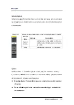
→System→ Number Format, to enter the following interface.           


Figure 2- 61 Set the number Format 

Summary of Contents for SDG800 Series

Page 1: ...User Manual SDG800 Series Function Arbitrary Waveform Generator UM02008 E02C 2017 SIGLENT TECHNOLOGIES CO LTD...

Page 2: ...00 User Manual I Declaration Copyright SIGLENT TECHNOLOGIES CO LTD All rights reserved Contents in this Manual are not allowed to be copied extracted and translated before being allowed by SIGLENT Com...

Page 3: ...ck the grounding conductor must be connected to the earth ground Make sure that the instrument is properly grounded before connecting the input or output terminals Observe all the ratings of the termi...

Page 4: ...ventilation Do not operate in wet damp conditions Do not operate in an explosive atmosphere Keep the product s surfaces clean and dry Not position the equipment so that it is difficult to operate the...

Page 5: ...CAT III CAT IV Not to use the equipment for measurements on mains circuits not to use the equipment for measurements on voltage exceed the voltage range describe in the manual Only probe assemblies wh...

Page 6: ...ms below may appear on the product DANGER Indicates an injury or hazard that may immediately happen WARNING Indicates an injury or hazard that may not immediately happen CAUTION Indicates that a poten...

Page 7: ...has a clear and simple front panel The user friendly panel layout and instructions versatile terminals direct graph interface built in instructions and help system have greatly simplified the operati...

Page 8: ...lf defined arbitrary waveform Multiple modulation function AM FM PM ASK FSK PWM DSB AM Sweep and Burst Multiple interfaces USB host USB device USBTMC Support USB storage device Software updating could...

Page 9: ...ital Input 15 1 8 To Use Store Utility Help Function 16 2 Operating Your Generator 17 2 1 To Set Sine Signals 18 2 2 To Set Square Signals 23 2 3 To Set Ramp Signals 26 2 4 To Set Pulse Signals 29 2 5...

Page 10: ...a Sweep Linear Wave 95 3 8 Example 8 Generate a Burst Wave 97 3 9 Example 9 Generate an AM Wave 99 3 10 Example 10 Generate a FM Wave 101 3 11 Example 11 Generate a PM Wave 103 3 12 Example 12 Generat...

Page 11: ...ing Started This chapter covers the following topics General Inspection Handle Adjustment The Front Rear Panel To Set a Waveform To Set Modulate Sweep Burst To Set Output To Use Digital Input To Use S...

Page 12: ...d with the instrument are listed in chapter 6 Appendix A Accessories If the contents are incomplete or damaged please notify your sales representative 3 Inspect the instrument In case any mechanical d...

Page 13: ...ent To adjust the handle position of SDG800 Function Arbitrary Waveform Generator please grip the handle by the sides and pull it outward Then make the handle rotate to the desired position Figure 1 1...

Page 14: ...rator has a clear and simple front panel See Figure 1 2 and Figure 1 3 The front panel has a knob and functional keys The 5 blue grey buttons on the right side of the screen are menu buttons named F1...

Page 15: ...gure 1 3 Front Panel of SDG800 Series Figure 1 4 Rear Panel of SDG800 Series USB Device Power Socket USB Host Waveform keys Number keys Knob Power LCD Display Menu Operation Function keys Output Contr...

Page 16: ...anel buttons Please note that the signs for the functional buttons on the operation panel are represented by squared words such as Sine which represents the transparent functional key with Sine on it...

Page 17: ...veform selection settings Figure 1 6 Waveform Selection Buttons 1 Press Sine button and the waveform window will display sine waveform SDG800 Series Generator can generate sine signal with a frequency...

Page 18: ...generate square signal with a frequency from 1 Hz to 10MHz and variable duty cycle Figure 1 8 Square Signal Display Interface As is shown in Figure 1 8 the default signal parameters are 1kHz frequenc...

Page 19: ...arameters are 1kHz frequency 4 0Vpp amplitude 0Vdc offset and 50 symmetry 4 Press Pulse button and the waveform window displays pulse waveform SDG800 Series Generator can generate pulse signal with a...

Page 20: ...aveform SDG800 Series Generator can generate noise signal with a band width up to 10MHz Figure 1 11 Noise Signal Display Interface As is shown in Figure 1 11 the default signal parameters are 128mV st...

Page 21: ...SDG800 User Manual 11 Figure 1 12 Arbitrary Waveform Signal Display Interface As is shown in Figure 1 12 the default signal parameters are 1kHz frequency 4 0Vpp amplitude and 0mVdc offset...

Page 22: ...Figure 1 13 Modulate Sweep Burst Button 1 Press Mod button the modulated waveforms will be generated The modulated waveform can be changed by modifying the parameters such as type internal external m...

Page 23: ...pulse noise and DC can not be swept In the sweep mode SDG800 Series generate signal with variable frequencies Figure 1 15 Sweep Waveform Display Interface 3 Press Burst button burst for sine square r...

Page 24: ...functions Figure 1 17 Output Buttons Press Output button activate or deactivate the output signal Term Explanation Burst Output waveforms with set cycle times Burst can last for certain times of wave...

Page 25: ...nob and the keypad The instruction below will help you familiarize with the digital input function Figure 1 18 Front Panel Digital Input 1 The up and down keys are used to shift parameters and the lef...

Page 26: ...iarize with these functions Figure 1 19 Store Recall Utility and Help Button 1 The Store Recall button is used to store waveform data and configure information 2 The Utility button is used to set the...

Page 27: ...e operations you are suggested to read chapter one Getting Started again This chapter covers the following topics Setting Sine Signal Setting Square Signal Setting Ramp Signal Setting Pulse Signal Set...

Page 28: ...sine waveforms are frequency period amplitude high level offset low level and phase Different sine signals are generated by setting these parameters As is shown in Figure 2 1 in the soft key menu sel...

Page 29: ...parameter the current operation is displayed in inverse color 2 Input the desired frequency Use the keypad to input the parameter value directly and press the corresponding button to select the parame...

Page 30: ...g the function if the current value is valid for the new waveform it will be used sequentially If you want to set the waveform by high level or low level press the Ampl HLevel or Offset LLevel button...

Page 31: ...et the Output Offset 1 Press Sine Offset to set the offset The offset shown on the screen when the instrument is powered is the default value or the set value beforehand When changing the function if...

Page 32: ...SDG800 User Manual 22 Figure 2 5 Setting the Offset...

Page 33: ...using the Square operation menu The parameters of Square waveforms are frequency period amplitude high level offset low level phase and duty As is shown in Figure 2 6 select Duty Cursor is located in...

Page 34: ...ault value or the set value beforehand When changing the function if the current value is valid for the new waveform it will be used sequentially Function Menu Settings Explanation Freq Period Set the...

Page 35: ...2 Input the desired Duty Cycle Use the keypad or the knob to input the desired value choose the unit and press the corresponding button The generator will change the waveform immediately Figure 2 8 S...

Page 36: ...tion menu The parameters for ramp waveforms are frequency period amplitude high level offset low level phase and symmetry As is shown in Figure 2 9 in the soft key menu select Symmetry Cursor is locat...

Page 37: ...quentially Function Menu Settings Explanation Freq Period Set the signal frequency or period The current parameter will be switched at a second press Ampl HLevel Set the signal amplitude or high level...

Page 38: ...8 2 Input the desired Symmetry Use the keypad or the knob to input the desired value choose the unit and press the corresponding button The generator will change the waveform immediately Figure 2 11 S...

Page 39: ...The parameters for pulse waveforms are frequency period amplitude high level offset low level pulse width Duty and Rise Fall As is shown in Figure 2 12 in the soft key menu select PulWidth Cursor is...

Page 40: ...Level Set the signal amplitude or high level The current parameter will be switched at a second press Offset LLevel Set the signal offset or low level The current parameter will be switched at a secon...

Page 41: ...ing Edge 1 Press Pulse Rise to set the Rise edge The rising edge shown on the screen when the instrument is powered is the default value or the set value beforehand When changing the function if the c...

Page 42: ...SDG800 User Manual 32 Figure 2 15 Setting the Rise edge...

Page 43: ...oise operation menu The parameters for noise waveforms are Stdev and mean As is shown in Figure 2 16 in the soft key menu select Stdev Cursor is located in the Stdev parameter area in the parameter di...

Page 44: ...SDG800 User Manual 34 Figure 2 17 Table 2 5 Menu Explanations of Noise Waveform Function Menu Settings Explanation Stdev Set the signal standard deviation Mean Set the signal mean...

Page 45: ...aveform parameters are set by using the Arb operation menu The Arb signal consists of two types the system built in waveform and the user definable waveform The parameters for Arb waveforms are freque...

Page 46: ...equency or period The current parameter will be switched at a second press Ampl HLevel Set the signal amplitude or high level The current parameter will be switched at a second press Offset LLevel Set...

Page 47: ...anations of Built in Arbitrary Waveform 1 To Select the Built in Waveform Press Arb Load Wform Built In and enter the following interface As is shown in Figure 2 22 there are five kinds of arbitrary w...

Page 48: ...waveform Winfun Triangle Select windows function triangle waveform Select Validate the built in waveform Function Menu Settings Explanation StairUp Select the built in stair up waveform StairDn Selec...

Page 49: ...ilt in logarithmic rise waveform Sqrt Select the built in square root waveform Root3 Select the built in Root3 waveform X 2 Select the built in X 2 waveform X 3 Select the built in X 3 waveform Sinc S...

Page 50: ...h white noise waveform Function Menu Settings Explanation Hamming Select the built in hamming window waveform Hanning Select the built in hanning window waveform Kaiser Select the built in kaiser wind...

Page 51: ...d enter the following interface As is shown in Figure 2 27 use the direction keys or knob to choose the corresponding arbitrary waveform and press Select Figure 2 27 Stored Wform Display Interface Ata...

Page 52: ...rm In FM users can set themodulating frequency frequency deviation modulating waveform and carrier waveform In ASK users can set the Key Freq and carrier waveform In FSK users can set the key frequenc...

Page 53: ...on Modulation Depth The amplitude range also called Percentage Modulation Modulation depth varies from 0 to 120 In the 0 modulation the output amplitude is the half of the set one In the 100 modulatio...

Page 54: ...ting Interface of FM Waveform Parameter Press Mod Type FM to enter the following menu Figure 2 31 Table 2 15 Menu Explanations of the FM Parameters Function Menu Settings Explanation FM Freq Set the m...

Page 55: ...ream modulating signal keeping frequency and phase constant The parameters for the ASK are as shown in Figure 2 32 Figure 2 32 Setting Interface of ASK Waveform Parameter Term Explanation Frequency De...

Page 56: ...e 2 33 Table 2 16 Menu Explanations of the ASK Parameters Function Menu Settings Explanation Key Freq Set the frequency at which the output amplitude shifts between the carrier amplitude and zero inte...

Page 57: ...ed the key frequency Figure 2 34 Setting Interface of FSK Waveform Parameter Press Mod Type FSK to enter the following interface Figure 2 35 Table 2 17 Menu Explanations of the FSK Parameters Function...

Page 58: ...2 36 Figure 2 36 Setting Interface of PM Waveform Parameter Press Mod Type PM enter the following interface Figure 2 37 Table 2 18 Menu Explanations of the PM Parameters Function Menu Settings Explana...

Page 59: ...are as shown in Figure 2 38 Figure 2 38 Setting Interface of PWM Waveform Parameter Press Mod Pulse PWM to enter the following menu Figure 2 39 Table 2 19 Menu Explanations of the PWM Parameters Func...

Page 60: ...eter Figure 2 41 Table 2 20 Menu Explanations of the DSB AM Parameters Function Menu Settings Explanation DSB Freq Set the modulating waveform frequency Frequency range 2mHz 20kHz Type DSB AM Amplitud...

Page 61: ...uency to the stop frequency at the sweep time you specify Sweep can be generated by sine square ramp or arbitrary waveforms pulse noise and DC are not allowed Figure 2 42 Setting Interface of Sweep Wa...

Page 62: ...Time Set the time span of the sweep in which the frequency changes from the start frequency to stop frequency Stop Freq Freq Span Set the stop frequency of the sweep Set the frequency span of the swee...

Page 63: ...imes of waveform cycle N Cycle burst or when external gated signals gated burst is applied any waveform could be used but noise can only be used in Gated Burst Press Burst button to enter the followin...

Page 64: ...cycles in a burst Burst Period Carrier Period Burst Number Start Phase Define the start point in a waveform The phase varies from 0 to 360 and the default setting is 0 For an Arbitrary Waveform 0 is t...

Page 65: ...in an N Cycle 1 to 50 000 or Infinite If you choose Infinite then a continuous waveform will be generated which will not stop until a trigger event happens If needed Burst Period will increase to cat...

Page 66: ...max delay is 240ns Set the Gated Burst Press Burst Gated to enter the following interface Figure 2 48 Table 2 25 Menu Explanations of the Gated Burst Parameters Function Menu Settings Explanation NCyc...

Page 67: ...the data documentation you save via CSV of the Oscilloscopes Figure 2 49 Save and Read Interface Figure 2 50 Table 2 26 Menu Explanations of Save and Recall Page 1 2 Function Menu Settings Explanation...

Page 68: ...0 non volatile memories The state storage will memorize the selected function including the arbitrary waveform frequency amplitude DC offset duty cycle symmetry and other modulation parameter used To...

Page 69: ...Figure 2 51 USB Storage Interface 1 Install the USB Device Insert the USB Device into the USB interface on the front panel and the screen will show USB flash device plug in and storage menu will show...

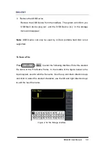
Page 70: ...by U Disk portable hard disk is not supported To Save a File Press Store Recall Store to enter the following interface Enter the desired file name in the File Name frame In the middle of the figure b...

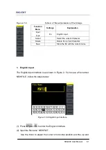
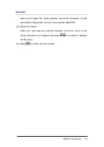
Page 71: ...ow the steps below Figure 2 54 English Input Interface 1 Press InType En to enter the English interface 2 Input the file name NEWFILE Use the Knob to adjust the cursor s horizontal position and the up...

Page 72: ...racter N and press Select Repeat this until you have inputted NEWFILE 3 Edit the File Name When you have entered a wrong character move the cursor to the wrong character to be deleted and press Delete...

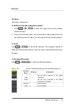
Page 73: ...the parameter setting for Load HighZ and Normal Inverse The System Setting provides the setting for Language Display Beep Screen Guard Format Power System Configure and default setting Test provides...

Page 74: ...tility DC DC On to enter the following interface Please note that there is a DC On sign at the middle left of the screen Figure 2 57 DC Setting Interface Function Menu Settings Explanation System Set...

Page 75: ...omatically To Set IO Press Utility IO Setup to set the IO interface The equipment stands for RAW protocol and TMC protocol user may setup corresponding protocol by IO Setup To Set Output Parameter Pre...

Page 76: ...ected one Steps for setting the load Press Utility Output Setup Load to enter the following interface Please note that the load parameter shown on the right bottom is the default setting when the powe...

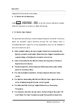
Page 77: ...he Sync signal should be connected to the Sync connector activated When the Sync Signal is disabled the output voltage of the Sync connector is level low In the Inverse Mode the Waveform that correspo...

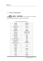
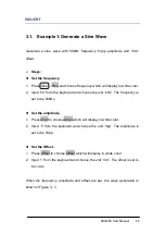
Page 78: ...ction Menu Settings Explanation Number format Set the number format Language Set the display language Power On Default Last All the settings return to default when powered All the settings return to t...

Page 79: ...e used when the instrument is powered Beep Activate or deactivate the sound when an error occurs from the front panel or the remote interface Activate or deactivate any sound made by the button or kno...

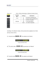
Page 80: ...oint press Separator On the example is as followed Figure 2 63 Set Format 2 as point press Separator On the example is as followed Figure 2 64 Set Format 3 as point press Separator Off the example is...

Page 81: ...wed Figure 2 67 Set Format 6 as point press Separator Space the example is as followed Figure 2 68 Set Format 2 Language Setup The SDG800 Series Generator offers two languages English and Simplified C...

Page 82: ...Function Sine Wave Frequency 1kHz Amplitude Offset 4Vpp 0Vdc Phase 0 Terminals High Z Modulation Default Carrier 1kHz Sine Wave Modulating 100Hz Sine Wave AM Depth 100 FM Deviation 500Hz Key Freq 100...

Page 83: ...SDG800 User Manual 73 Source Internal...

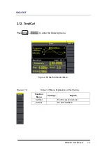
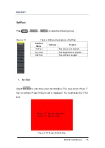
Page 84: ...Press Utility Test Cal to enter the following menu Figure 2 69 Test Cal function Menu Figure 2 70 Table 2 35 Menu Explanations of Test Setting Function Menu Settings Explain SelfTest Perform system se...

Page 85: ...elf Test 1 Scr Test Select Scr Test to enter the screen test interface The clew words Press 7 Key to continue Press 8 Key to exit is displayed You could press the 7 for test Figure 2 72 Screen Test In...

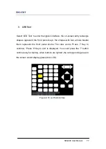
Page 86: ...knobs Test all keys and knobs and you should also verify that all the backlit buttons illuminate correctly Note When you operate the screen would display the white color LCD The tested button or knob...

Page 87: ...nt panel keys the shapes with two arrows beside them represent the front panel knobs The clew words Press 7 Key to continue Press 8 Key to exit is displayed You could press the 7 button continuously f...

Page 88: ...Utility 1 2 Test Cal SelfCal to enter SelfCal as is shown in Figure 2 5 SelfCal do self calibration environment you use the generator changes system may calibrate data based on change of current envir...

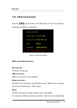
Page 89: ...face Edition Information introduce Boot strap No The times of boot strap Software version Software version of current equipment Hardware version 02 00 00 21 25 represents ordinally PCB version BOM ver...

Page 90: ...is 10MHz Serial No Bit 1 6 represent maker and series of the product Bit 7 10 represent production date Bit 11 14 represent serial number of product For example SDG00004130008 represents the eighth g...

Page 91: ...e generator 2 Press the Utility button to enter the Utility Menu 3 Press 1 2 option button to enter the second page of Utility Menu 4 Press the Update option button 5 Press Brower option button to sel...

Page 92: ...built in help system Or you can get help about the operation of the front panel buttons with the help list Press Help to enter the following interface Figure 2 77 Help Menu Figure 2 78 Table 2 37 Hel...

Page 93: ...the following topics Example 1 Generate a Sine Wave Example 2 Generate a Square Wave Example 3 Generate a Ramp Wave Example 4 Generate a Pulse Wave Example 5 Generate a Noise Wave Example 6 Generate...

Page 94: ...se the unit kHz The frequency is set to be 50kHz Set the amplitude 1 Press Ampl to choose Ampl which will display in white color 2 Input 5 from the keyboard and choose the unit Vpp The amplitude is se...

Page 95: ...SDG800 User Manual 85 Figure 3 1 Sine Waveform...

Page 96: ...ss Ampl to choose Ampl which will display in white color 2 Input 2 from the keyboard and choose the unit Vpp The amplitude is set to be 2Vpp Set the offset 1 Press Offset to choose Offset which will d...

Page 97: ...SDG800 User Manual 87 Figure 3 2 Square Waveform...

Page 98: ...s set to be 10 s Set the amplitude 1 Press Ampl to choose Ampl which will display in white color 2 Input 100 from the keyboard and choose the unit mVpp The amplitude is set to be 100mVpp Set the offse...

Page 99: ...choose Symmetry which will display in white color 2 Input 30 from the keyboard and choose the unit 30 The symmetry is set to be 30 When the period amplitude offset phase and symmetry are set the wave...

Page 100: ...to be 5 kHz Set the high level 1 Press Ampl and choose the HLevel which will display in white color 2 Input 5 from the keyboard and choose the unit V The high level is set to be 5V Set the low level 1...

Page 101: ...oose Rising Edge which will display in white color 2 Input 20 from the keyboard and choose the unit ns The delay is set to be 20ns When the frequency high level low level pulse width and delay are set...

Page 102: ...stdev 1 Press Noise Stdev 2 Input 10 from the keyboard and choose the unit mV The amplitude is set to be 10 mV Set the mean 1 Press Mean 2 Input 5 from the keyboard and choose the unit mV The offset...

Page 103: ...Set the frequency 1 Press Freq and choose Frequency which will display in white color 2 Input 5 from the keyboard and choose the unit MHz The frequency is set to be 5MHz Set the amplitude 1 Press Amp...

Page 104: ...SDG800 User Manual 94 the wave generated is shown in Figure 3 6 Figure 3 6 Sinc Waveform...

Page 105: ...ch will display in white color Input 5 from the keyboard and choose the unit kHz to set the frequency 5kHz 2 Press Ampl to choose Ampl which will display in white color Input 5 from the keyboard and c...

Page 106: ...top Freq Input 10 from the keyboard and choose the unit kHz to set stop freq 10kHz Set the Sweep Mode Press 1 2 Linear and choose Linear When all parameters above are set the linear sweep wave generat...

Page 107: ...10 from the keyboard and choose the unit kHz to set the frequency 10kHz 2 Press Ampl to choose Ampl which will display in white color Input 1 from the keyboard and choose the unit Vpp to set the ampli...

Page 108: ...Input 5 from the keyboard and choose the unit Cycle to set the burst cycle 5 Set the delay Press Delay and input 100 from the keyboard and choose the unit s to set the delay 100 s When all parameters...

Page 109: ...isplay in white color Input 1 from the keyboard and choose the unit Vpp to set the amplitude 1Vpp 4 Press Offset and choose Offset which will display in white color Input 0 from the keyboard and choos...

Page 110: ...SDG800 User Manual 100 Figure 3 9 AM Waveform...

Page 111: ...will display in white color Input 1 from the keyboard and choose the unit Vpp to set the amplitude 1Vpp 4 Press Offset and choose Offset which will display in white color Input 0 from the keyboard and...

Page 112: ...SDG800 User Manual 102 3 10 Figure 3 10 FM Waveform...

Page 113: ...splay in white color Input 5 from the keyboard and choose the unit Vpp to set the amplitude 5Vpp 4 Press Offset and choose Offset which will display in white color Input 0 from the keyboard and choose...

Page 114: ...SDG800 User Manual 104 Figure 3 11 PM Waveform...

Page 115: ...which will display in white color Input 5 from the keyboard and choose the unit Vpp to set the amplitude 5Vpp 4 Press Offset and choose Offset which will display in white color Input 0 from the keybo...

Page 116: ...SDG800 User Manual 106 Figure 3 12 FSK Waveform...

Page 117: ...cy 5kHz 3 Press Ampl and choose Ampl which will display in white color Input 5 from the keyboard and choose the unit Vpp to set the amplitude 5Vpp 4 Press Offset and choose Offset which will display i...

Page 118: ...SDG800 User Manual 108 Figure 3 13 ASK Waveform...

Page 119: ...5 from the keyboard and choose the unit Vpp to set the amplitude 5Vpp 4 Press Offset and choose Offset which will display in white color Input 0 from the keyboard and choose the unit Vdc to set the o...

Page 120: ...SDG800 User Manual 110 When all parameters above are set the wave generated is shown in Figure 3 14 Figure 3 14 PWM Waveform...

Page 121: ...kHz 3 Press Ampl and choose Ampl which will display in white color Input 4 from the keyboard and choose the unit Vpp to set the amplitude 4Vpp 4 Press Offset and choose Offset which will display in wh...

Page 122: ...SDG800 User Manual 112 Figure 3 15 DSB AM Waveform...

Page 123: ...damage or defect or the instrument does not operate properly or fails performance tests notify the SIGLENT sales representative If the shipping container is damaged or the cushioning materials show si...

Page 124: ...tch is turned on 3 After the inspections above restart the waveform generator 4 If the generator still doesn t work after the checking please connect with SIGLENT company 2 If there is no signal wave...

Page 125: ...NT will provide repair or replacement as described in the complete warranty statement To arrange for service or obtain a copy of the complete warranty statement please contact your nearest SIGLENT sal...

Page 126: ...16 Contact SIGLENT MTR Add 3 F Building 4 Antongda Industrial Zone Liuxian Road 68 District Baoan District Shenzhen P R CHINA Service Tel 0086 755 3661 5186 Post Code 518101 E mail sales siglent com h...

Page 127: ...ppendix Appendix A Accessories SDG800 Series Function Arbitrary Waveform Generator Accessories Standard Accessories A Quick Start A Calibration Certificate A Power Cord that fits the standard of desti...

Page 128: ...connect it from all power sources and clean it with a mid detergent and water Make sure the instrument is completely dry before reconnecting it to a power source To clean the exterior surface perform...

Reviews: