background image


 118

3.3 Catch the single signal 


To capture a single event, you need to gather some pre-test knowledge of the 

signal in order to correctly set up the trigger level and slope .if you are not sure the 

instance of the signal, you can observe it through auto or normal trigger mode to ensure   

the trigger level and slope. 

The following steps show you how to use the oscilloscope to capture a single event. 

1. Set the Probe option attenuation to 10X and set the switch to 10X on the 

probe. 

  2. Trigger set up


(1) Press “TRIG MENU” button to show the “Trigger Menu” 

(2) Under this menu, set the trigger type to “edge”, Edge type is “Rising”, 

source is “CH1”, trigger mode is “Single”, coupling is “DC” 

(3) Adjust the horizontal time base and vertical scale to the satisfied range 

(4) Turn the “LEVEL” knob to adjust the trigger level 

(5) Press the “RUN/STOP” button to start capturing 

When the trigger conditions are satisfied, data appears on the display 

representing; the data points that the oscilloscope obtained with one acquisition 

and press the RUN/STOP button again rearms the trigger circuit and erases the 

display.


Summary of Contents for SDS1000 Series

Page 1: ...I User Manual SDS1000 Series Digital Storage Oscilloscope Version No V 1 2 Siglent Technologies Co Ltd...

Page 2: ...II Declaration Copyright by Siglent Technologies Co Ltd All rights reserved Contents in this Manual are not allowed to copy extract and translate before being allowed by Siglent...

Page 3: ...DS1000CM Series 18Kpts SDS1000CE Series 24Kpts SDS1000CF Series Trigger types Edge Pulse Video Slope and Alternative Unique Digital Filter function and Waveform recorder function Pass Fail function Au...

Page 4: ...l Output LAN Port SDS1000CF Series have this configuration SDS1000 Series Digital Storage Oscilloscope Standard Accessories 1 1 10 1 probe 2 4 PCS Power Cable that fits the standard of destination cou...

Page 5: ...duct This product is grounded through the grounding conductor of the power cord To avoid electric shock the grounding conductor must be connected to earth ground Before making connections to the input...

Page 6: ...t These terms may appear on the product DANGER Indicates an injury hazard immediately accessible as you read the marking WARNING Indicates an injury hazard not immediately accessible as you read the m...

Page 7: ...instrument This symbol shows that the switch is a standby power switch located on the front of the oscilloscope Pressing this button toggles the oscilloscope s state between operation and standby mode...

Page 8: ...f a wide variety of measurements to give you ideas on how to solve your measure problems Prompting messages and Troubleshooting chapter describes prompting messages and describes some ways of troubles...

Page 9: ...ctor 16 2 3 Auto setup 17 2 4 Default setup 19 2 5 Universal knob 20 2 6 Vertical System 21 2 6 1 CH1 CH2 CH3 CH4 Channel 21 2 6 2 Using Vertical Position knob and Volt div knob 27 2 6 3 Math Function...

Page 10: ...nal 118 3 4 Analyze the signal detail 119 3 4 1 Looking at a Noisy Signal 119 3 4 2 Separating the Signal from Noise 119 3 5 Triggering on a Video Signal 120 3 5 1Triggering on Video Field 120 3 5 2 T...

Page 11: ...pe and portable bench type instruments which could be used for measuring as the GND voltage This Chapter shows you how to operate following tasks Accidence of panel and Display information Simple chec...

Page 12: ...e panel contains knobs and buttons There is a list of five ashen buttons as menu operational buttons on the right of display screen You can set different options of the current menu in virtue of them...

Page 13: ...ront panel buttons and knob locations for SDS1000CF series correspond with the following explanations 1 Security Lock Receptacle 2 Pass Fail Output 3 RJ 45 Connector LAN Ethernet Port 4 USB Devic and...

Page 14: ...scillscope Previously numbered front panel buttons and knob locations for SDS1000C CM CE series correspond with the following explanations 1 Pass Fail Output 2 RS 232 Connector 3 USB Device Connector...

Page 15: ...ker shows horizontal trigger position Turn the HORIZONTAL POSITION knob to adjust the position of the marker 4 Print Key Indicates whether the Print Key option is set to Print Pictrure or Save Picture...

Page 16: ...the oscilloscope could work smoothly please operate as following 1 Power On the oscilloscope Press DEFAULT SETUP to show the result of the self check The probe default attenuation is 1X Picture 1 2 1...

Page 17: ...KHz frequency and about 3V peak peak square wave in couple seconds Picture 1 2 3 4 Press CH1 two times to cancel the channel 1 Press CH2 CH3 or CH4 to change screen into channel 2 channel 3 or channel...

Page 18: ...that the Probe attenuation option matches the attenuation of the probe You can push a vertical menu button such as the CH 1 MENU button and select the Probe option that matches the attenuation factor...

Page 19: ...e probe and connect the probe to channel 1 on the oscilloscope If you use the probe hook tip ensure a proper connection by firmly inserting the tip onto the probe 2 Attach the probe tip to the PROBE C...

Page 20: ...12 Over compensated Compensated correctly under compensated Picture 1 3 3 4 If necessary adjust your probe Repeat as necessary...

Page 21: ...to learn about the following oscilloscope functions Menu and control button Connector Auto Setup Default Setup Universal knob Vertical System Horizontal System Trigger System Acquiring signals System...

Page 22: ...zontal menu You can use the Horizontal menu to display the waveform and to zoom a segment of a waveform TRIG MENU Press to display the Trigger menu You can use the Trigger menu to set the trigger type...

Page 23: ...remain displayed unless the Type option is set to Off after leaving the Cursor Menu but are not adjustable DISPLAY Press to open the Display menu You can use the Display menu to set grid and waveform...

Page 24: ...gger Menu to select the Ext or Ext 5 trigger source Probe Component Voltage probe compensation output and ground Use to electrically match the probe to the oscilloscope input circuit Note If you conne...

Page 25: ...function Menu Option Description Multi cycle sine Auto set the screen and display several cyc signal Single cycle sine Set the screen and auto display single cyc signal Rising edge Auto set and show...

Page 26: ...o Vectors for an FFT spectrum otherwise unchanged Vertical Coupling Adjusted to DC or AC according to the input signal Bandwidth Limit Off full V div Adjusted VOLTS DIV adjustability Coarse Signal inv...

Page 27: ...p To recall this setup press the DEFAULT SETUP button The options buttons and controls that change settings when you press the DEFAULT SETUP button refer to appendix B The DEFAULT SETUP button does no...

Page 28: ...doff time moving cursors setting the pulse width Setting the Video Linage adjusting thr upper and lower frequency limit adjust X and Y masks when using the pass fail function etc You can also turn the...

Page 29: ...l and attenuates signals below 10 Hz GND disconnects the input signal BW limit On Off Limits the bandwidth to reduce display noise filters the signal to reduce noise and other unwanted high frequency...

Page 30: ...on to return the first page menu Option Setting Introduction Digital Filter On Off Turn on the digital filter Turn off the digital filter Type Setup as LPF Low Pass Filter Setup as HPF High Pass Filte...

Page 31: ...ocks the DC component of the input signal Press CH1 Coupling DC Set to DC couple mode Both DC and AC component could be obstructed Press CH1 Coupling GND Set to GROUND mode It disconnects the input si...

Page 32: ...tical sensitivity range of SDS1000CM is 2mV div 10V div scale Take the CH1 for example Press CH1 Volts Div Coarse It is the default setting of Volts Div and it makes the vertical scaling in a 1 2 5 st...

Page 33: ...fficient is 10 1 the input coefficient should be set to 10X so that the mistake of the Volts div information and measure testing should be forbidden Take the CH1 for example when you use the 100 1 pro...

Page 34: ...2 Filter display the digital filter menu Select Filter Type then select Upper Limit or Lower Limit and turn the Universal knob to adjust them Press CH1 Next Page page1 2 Filter Off Turn off the Digit...

Page 35: ...position to zero Volts div knob 1 Use the Volts div knobs to control how the oscilloscope amplifies or attenuates the source signal of channel waveforms When you turn the volts div knob the oscillosco...

Page 36: ...nction CHY Invert on off Invert the CHY waveform Turn off CHY Invert function Table 2 7 MATH function instruction Operation Setting Introduction CHX CHY CHX waveform adds CHY waveform CHX CHY The chan...

Page 37: ...in the system Show the Noise in the DC Power supply Test the filter and pulse response in the system Analyze vibration Table 2 8 FFT function menu 1 FFT Option Setting Introduction Source CH1 CH2 CH3...

Page 38: ...aveform that you want to analyze in the center eight divisions of the screen The oscilloscope calculates the FFT spectrum using the center 1024 points of the time domain waveform Turn the Volts div kn...

Page 39: ...window Windows reduce spectral leakage in the FFT spectrum The FFT assumes that the YT waveform repeats forever With an integral number of cycles the YT waveform starts and ends at the me amplitude a...

Page 40: ...magnitude worst frequency resolution Single frequency waveforms to find higher order harmonics 4 Magnifying and Positioning an FFT Spectrum You can magnify and use cursors to take measurements on the...

Page 41: ...equency of input signal 7 If FFT display on full screen press CH1 button again to remove channel waveform display 8 Press the CURSOR button to enter Cursor menu 9 Press the Cursor Mode button to selec...

Page 42: ...ency Picture 2 6 12 NOTE The FFT of a waveform that has a DC component or offset can cause incorrect FFT waveform magnitude values To minimize the DC component choose AC Coupling on the source wavefor...

Page 43: ...waveform Save Stores source waveform to the chosen reference location REFA REFB REFC REFD on off Recall the reference waveform on the screen Turn off the reference waveform Press the Ref button to di...

Page 44: ...the bottom option button to select REFA On REFB On REFC On or REFD On to recall the reference waveform Picture 2 6 14 Note X Y mode waveforms are not stored as reference waveforms You cannot adjust t...

Page 45: ...me time Turn off this function that only display main timebase waveform on the screen MemDepth Normal Long Mem Set memory depth to normal Set memory depth to long Memory depth in order to get more wav...

Page 46: ...ition of the trigger relative to the center of the screen The resolution of this control varies with the time base setting 2 When you press the horizontal POSITION Knob you can set the horizontal posi...

Page 47: ...so a arrow on the scale top to show the vertical position If you want to see a section of the waveform in detail follow these steps SDS1000C CE CF series Operate steps 1 Press the HORI MENU button to...

Page 48: ...the Horizontal menu 2 Turn the S div knob to change the main timebase scale 3 Press the Delayed option button to select On 4 Turn the Horizontal Position knob adjust window s position to select the w...

Page 49: ...ningful waveforms Here are three buttons and one Knob in the Trigger area Showing as Picture 2 29 Picture 2 8 1 TRIG MENU Button Press the TRIG MENU Button to display the Trigger Menu LEVEL Knob The L...

Page 50: ...ger and 1s delayed trigger can be surveyed by adjusting the horizontal position The feature is very useful because you can see the events that led up the trigger point everything to the right of the t...

Page 51: ...gger signal Auto Use this mode to let the acquisition free run in the absence of a valid trigger This mode allows an untriggered scanning waveform at 100 ms div or slower time base settings Normal Use...

Page 52: ...t or 4 Set up Trigger mode Press the Trigger mode option button to select Auto Normal Single Auto The waveform refresh at a high speed whether the trigger condition is satisfied or not Normal The wave...

Page 53: ...ive pulse width less than pulse width setting Positive pulse width larger than pulse width setting Positive pulse width equal to pulse width setting Negative pulse width less than pulse width setting...

Page 54: ...ormal single Select the type of triggering Normal mode is best for most Pulse Width trigger applications Set up Enter the Trigger setup menu Next Page Page 2 2 Press this button to return the first pa...

Page 55: ...Ext 5 use the signal applied to the EXT TRIG connector as the source Normal Normal triggers on the negative edge of the sync pulse Polarity Inverted Inverted triggers on the positive edge of the sync...

Page 56: ...c option button to select All Lines Line Num Odd Field 100 ms div or slower time base settings Normal Use this mode when you want to see only valid triggered waveforms when you use this mode the oscil...

Page 57: ...ve slope of negative slope according to setup time of the oscilloscope Table 2 19 Slope trigger function menu 1 Option Setting Instruction Type Slope Trigger on positive slope of negative slope accord...

Page 58: ...just LEVEL A LEVEL B or adjust them at the same time Auto Use this mode to let the acquisition free run in the absence of a valid trigger This mode allows an untriggered scanning waveform at 100 ms di...

Page 59: ...L knob Alternative trigger The trigger signal comes from two vertical channels when you use alternative trigger In this mode you can observe two irrelative signals at the same time You can select diff...

Page 60: ...H4 as source for alternative trigger Source CHX CHY Set trigger type information for CHXsignal Set trigger type information for CHY signal Mode Pulse Set trigger type of the vertical channel signal to...

Page 61: ...s CHX CHY Select any two channels from CH1 CH2 CH3 CH4 as source for alternative trigger Source CHX CHY Set trigger type information for CHX signal Set trigger type information for CHY signal Mode Slo...

Page 62: ...l signals follow these steps 1 Input two irrelative signals to channel 1and channel 2 2 Press the AUTO button 3 Press the TRIG MENU button to enter trigger menu 4 Press the Type option button to selec...

Page 63: ...he center of the display actually This appears to move the waveform to the right or left on the display 2 8 5 Slope Level The Slope and Level controls help to define the trigger The Slope option Edge...

Page 64: ...cope triggers only on the first pulse in the train Holdoff time Trigger position Trigger level Picture 2 8 11 If you want to change holdoff time please follow next operations 1 Press the TRIG MENU but...

Page 65: ...is acquisition mode the oscilloscope samples the signal in evenly spaced intervals to construct the waveform This mode accurately represents signals most of the time Option Setting Introduction Sampli...

Page 66: ...Picture 2 9 2 Sampling modes Peak Detect Peak Detect mode capture the maximum and minimum values of a signal Finds highest and lowest record points over many acquisitions Advantage In this way the os...

Page 67: ...uously Press the button again to stop the acquisition SINGLE Button Press the SINGLE button to acquire a single waveform Each time you push the SINGLE button the oscilloscope begins to acquire another...

Page 68: ...his happens the oscilloscope displays a waveform with a frequency lower than the actual input waveform or triggers and displays an unstable waveform Sampled points Apparent low frequency waveform due...

Page 69: ...on to select Real Time or Equ Time Set up Sampling rate Adjust the sampling rate by pressing the Sa Rate option button and turning the Time div front panel knob The sampling rate is shown at the corre...

Page 70: ...ace between adjacent sample points in the display Dots There is no link between adjacent sample points Persist Off 1 sec 2 sec 5 sec Infinite Sets the length of time each displayed sample point remain...

Page 71: ...T format displays the vertical voltage in relation to time horizontal scale XY format displays a dot each time a sample is acquired on channel 1 and channel 2 or channel 3 and channel 4 Screen Normal...

Page 72: ...enter second display menu 2 Press the Format option button to select YT or XY 5 Set up Screen Press the Screen option button to select Normal or Inverted to set the screen display color 6 Set up Grid...

Page 73: ...sequence adjusted SDS1000CM series support 25KSa s 100MSa s 1 2 5 5 sequence adjusted SDS1000CE series support 5KSa s 1GSa s 1 2 5 5 sequence adjusted and SDS1000CF series support 10Ksa s 1GSa s 1 2 5...

Page 74: ...cale factor For example if you counted five major vertical graticule divisions between the minimum and maximum values of a waveform and knew you had a scale factor of 100mV div then you could easily c...

Page 75: ...or A Cur B Select this option turn the Universal knob to adjust cursor B In this mode the screen displays two horizontal parallel cursors or vertical parallel cursors to measure voltage or time You ca...

Page 76: ...to input signal channel 5 Select Cur A turn the Universal knob to adjust Cursor A 6 Select Cur B turn the Universal knob to adjust Cursor B 7 The measurement values are displayed on the top of the lef...

Page 77: ...sor s horizontal position on the waveform by turning the Universal knob The oscilloscope displays the values on the top of the right screen To do track cursor measurement follow these steps 1 Press CU...

Page 78: ...value between two cursors Picture 2 11 3 Auto mode Table 2 34 Auto mode function menu Option Setting Instruction Cursor Mode Auto Set to auto cursor measure mode This mode will take effect with automa...

Page 79: ...ause the measurements use the waveform record points they are more accurate than the graticule or cursor measurements Press the MEASURE for the Automatic Test There are three auto measurement types Vo...

Page 80: ...OVShoot RPREShoot FPREShoot Press the Type button or turn the Universal knob to select Voltage measure parameter Display the corresponding icon and measure value of your selected Voltage measure param...

Page 81: ...rn to the All Measure main menu Table 2 40 Introduction of the Measure Type Option Setting Instruction Source CHX CHY Select any two input signal source for Delay measure Type Phase FRR FRF FFR FFF LR...

Page 82: ...at the waveform 50 level Wid Width Measures the time between the first falling edge and the next rising edge at the waveform 50 level Duty Measures the first cycle waveform Positive Duty Cycle is the...

Page 83: ...ding icon and value will display below the measure parameter Picture 2 11 7 6 Press the Return option button to return the home page of Auto Measurement menu The selected parameter and the correspondi...

Page 84: ...u 2 Press the top option button to enter the second page of Auto Measure menu 3 Press All Mea option button to enter the All Measure menu 4 Press Source option button to select input signal channel 5...

Page 85: ...lloscope and you can save setup data waveform data waveform interface image CSV file to a USB flash drive furthest at a time Setup data and waveform data can be recalled to the current oscilloscope or...

Page 86: ...nd it s highlighted in the main screen area press the Load option button and the setup is recalled from the USB flash drive Both Directory and Files have Rename and Return option buttons on Page2 2 Us...

Page 87: ...the Universal knob to move through character selections When the desired character is highlighted press the Universal knob or press he InputChar option button to add it to the specific position in th...

Page 88: ...tup to device function menu Option Setting Introduction Type Setups Menu for the Storage Recall setting in the oscilloscope Save to Device Save setup to the oscilloscope s internal memorizer Setup No...

Page 89: ...follow next steps 1 Press the SAVE RECALL button to enter the SAVE RECALL display menu 2 Press the Type option button to select Setups 3 Press the Save to option button to select Device 4 Press the S...

Page 90: ...l file option button to delete a file 10 Press the next page option button and press the Rename option button to modify the name of the file or the folder 11 Turn the Universal knob to select the fold...

Page 91: ...veforms to Device Table 2 44 Save waveform to device function menu Option Setup Introduction Type waveforms Menu for the Storage Recall waveforms in the oscilloscope Save to Device Save waveforms to t...

Page 92: ...option button or turn the Universal knob to select No 1 6 Turn the Volts div knob or S div knob to adjust the waveform that you want to need 7 Press the Save option button Recall wavefroms follow nex...

Page 93: ...onds 5 Press the Save to option button to select File 6 Press the Save option button then you ll go into the Save Recall interface 7 Create a file then press the Confirm button about five seconds ther...

Page 94: ...nter select Print Picture and press the PRINT button to print the screen image Print Key Save Picture When the USB flash drive insert to the USB Host interface now the USB flash drive open status icon...

Page 95: ...e function menu Option Setting Introduction Type CSV Menu for the Storage CSV file to USB flash drive Data Depth Displayed Maximum Set to store displayed waveform data to CSV file Set to store maximum...

Page 96: ...button to select On or Off 6 Press the Save option button then you ll go into the Save Recall interface 7 Create a file name then press the Confirm button About five seconds there is a prompting mess...

Page 97: ...es of the oscilloscope settings Sound Open the key press voice Close the key press voice Counter On Off Turn on Frequency Counter Turn off Frequency Counter Language English Fran ais Deutsch Espa ol P...

Page 98: ...rint Setup Enter the print setup menu to set print options Printer The oscilloscope connects to the printer using USB cable When you execute print function please select Printer Now the print icon dis...

Page 99: ...Setting Introduction IP Address Set oscilloscope IP Address adopt LAN port to connect the oscilloscope Subnet Mask Set corresponding IP Subnet Mask Gate Way Set corresponding IP Gate Way Port Connect...

Page 100: ...Four channels Option Setting Introduction Screen saver 1min 2min 5min 10min 15min 30min 1hour 2hour 5hour Off Set the time of Screen saver Date Time Set Date Time in this menu Quick Cal On Off Do Qui...

Page 101: ...nob can change month day Hour Minute 00 00 Set the present displaying hour minute adjust universal knob can change hour minute Display On Off Turn on date time display information Turn off date time d...

Page 102: ...are version List the software version Hardware Version List the hardware version Product type List the product type Serial No List the product serial number 2 13 2 Language The oscilloscopes have twel...

Page 103: ...ize Default L 2L Hagaki Postcard Card Size 10 x 15 cm 4 x 6 8 x 10 Letter 11 x 17 A0 A1 A2 A3 A4 A5 A6 A7 A8 A9 B0 B1 B2 B3 B4 B5 B6 B7 B8 B9 89 mm Roll L 127 mm Roll 2L 100 mm Roll 4 210 mm Roll A4 D...

Page 104: ...w these steps 1 Connect the oscilloscope to a PictBridge compatible printer 1 Insert one end of a USB cable into the USB Device port on the oscilloscope 2 Insert the other end of the cable into the Pi...

Page 105: ...n Self Calibration procedure can optimize the signal path at the most measurement precision You can run this procedure at any time If the operating temperature changes by more than 5 C or the units ru...

Page 106: ...elf Test Table2 55 Operation Steps 1 Screen Test Select Screen Test to enter the screen test interface The clew words Press SINGLE Key to continue Press RUN STOP Key to exit is displayed you could pre...

Page 107: ...s for scale knobs Test all keys and knobs and you should also verify that all the backlit buttons illuminate correctly Note When you operate the screen would display the white Color LCD and black sing...

Page 108: ...scale knobs The clew words Press SINGLE Key to continue Press RUN STOP Key to exit is displayed you could press the Single button continuously for testing when buttons are lighted the corresponding a...

Page 109: ...le oscilloscope is updating Ethernet port upgrate function Users can upgrate the DSO through the Ethernet port on the DSO back pannel operation Steps are as follows 1 open the DSO 2 connect the DSO to...

Page 110: ...tting Instruction Enable On Off Turn on Pass Fail function Turn off Pass Fail function Source CH1 CH2 CH3 CH4 Slect signal input channel Operate Press to run the Pass Fail test Press to stop the Pass...

Page 111: ...occur Mask Setting Press this button to enter the Mask Setting menu Return Return to the Pass Fail main menu Next Page Page 2 2 Return the first page of the Pass Fail menu Picture 2 13 16 Table 2 58 M...

Page 112: ...mask Next Page Page 1 2 Press this button to enter the second page of Mask Setting menu Picture2 13 17 Table 2 59 Mask Setting function menu 2 Option Setting Instruction Save Store created mask settin...

Page 113: ...option button to enter the second page of the Pass Fail menu 8 Press the Mask Setting option button to enter the first page of Mask menu 9 Press the X Mask button turn the Universal knob to adjust th...

Page 114: ...eeping an eye watching it Waveform recorder Record the waveforms with specified interval Table 2 60 Waveform recorder function menu Option Setting Instruction Mode Record Play Back Storage Off Set Rec...

Page 115: ...l knob to adjust time interval between record frames 7 Select End Frame select the Universal knob to adjust the max record frame 8 Press in Operate option to record waveform Play Back Play back curren...

Page 116: ...t Page Page 2 2 Return to the first page of Play Back function menu Picture 2 13 22 To play back current record waveforms follow these steps 1 Press UTILITY button to enter Utility menu 2 Press the Mo...

Page 117: ...form means oscilloscope can save and replay waveform every time it captured It is similar to waveform recording instrument and the biggest recording size of its internal memory is 6M Table 2 65 wavefo...

Page 118: ...rm of recording on split screen and channel recalling CH1 is displayed in upper half screen CH2 is displayed in lower half screen Record Mode Roll Single Swee Recorder saves the channel waveform persi...

Page 119: ...e of Utility menu 3 Press the Recorder button to enter the Recorder manual 4 Press the Option button to select the parameter which you want by yourself 5 Press the Recorder button to enter the Record...

Page 120: ...e them when you first enter the help status because you press the SINGLE button can enter next page of help information and Press the RUN STOP button can return to the first page of help information w...

Page 121: ...features of the oscilloscope and give you ideas for using it to solve your own test problems Taking simple measurements Taking cursor measurements Capturing a single shot signal Analyzing signal detai...

Page 122: ...ill you are satisfied with the waveforms 2 Taking Automatic Measurements The oscilloscope can take automatic measurements of most displayed signals To measure signal frequency and peak to peak amplitu...

Page 123: ...menu Press the top second option button Press the Voltage option button to enter the Voltage measure menu Press the Source option button to select input signal channel Press the Type option button to...

Page 124: ...Cursor Menu 2 Press the Mode button to select Manual 3 Press the Type option button and select Time 4 Press the Source option button and select CH1 5 Press the CurA button and turn the universal knob...

Page 125: ...option button and select CH1 5 Press the CurA option button and turn the universal knob to place the cursor A on the highest peak of the ring 6 Press the CurB option button and turn the universal knob...

Page 126: ...and set the switch to 10X on the probe 2 Trigger set up 1 Press TRIG MENU button to show the Trigger Menu 2 Under this menu set the trigger type to edge Edge type is Rising source is CH1 trigger mode...

Page 127: ...cessary press the DISPLAY button to see Display menu Turn the Universal knob to adjust waveform intensity and grid brightness to see the noise more clearly 4 Peak detect emphasizes noise spikes and gl...

Page 128: ...ct NTSC 6 Turn the horizontal S Div knob to see a complete field across the screen 7 Turn the vertical Volts Div knob to ensure that the entire video signal is visible on the screen 3 5 2 Triggering o...

Page 129: ...nnect the channel 2 probe to the output 5 Press the AUTO button 6 Turn the Volts div knobs to display approximately the same amplitude signals on each channel 7 Press the DISPLAY button 8 Press the Fo...

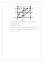
Page 130: ...the two signals From the formula above you could get arcsine A B or arcsine C D If the main axis of the ellipse is at and quadrant must be in the range of 0 2 or 3 2 2 if the main axis is at and quad...

Page 131: ...obe option attenuation to 10X 2 Press the CH 2 button and set the Probe option attenuation to 10X 3 Set the switches to 10X on the probes 4 Press the AUTO button 5 Press the MATH button to see the Mat...

Page 132: ...full range while turning the vertical scale knob Holdoff time at limit Turn the Universal knob when holdoff time has been to max or min value now the system will clew this information Functions isn t...

Page 133: ...ccessful Please set Back USB to printer Press the S div knob will appear this information on the screen when the Print Key option is set to Print Picture and the Back USB option is set to Computer USB...

Page 134: ...r not 4 Check the tested goods produce the signal or not 5 Gather the signal again 3 The value of the tested voltage is 10 times higher lower than the real one please do as following steps Check the a...

Page 135: ...the Auto button to set up automatically 6 After the Acquisition is set to Averages or Display Persistence time is set too long the waveform refreshes slowly It is normal in these settings 7 The signa...

Page 136: ...ective period Siglent will provide repair or replacement as described in the complete warranty statement To arrange for service or obtain a copy of the complete warranty statement please contact your...

Page 137: ...129 5 2 Contact us MTR Add Building A8 Tanglang Industrial zone Xili Nanshan Shenzhen 518055 P R China Tel 800 999 0807 E mail support siglent com http www siglent com...

Page 138: ...tion interval All specifications are guaranteed unless noted typical Specifications Inputs Input Coupling AC DC GND Input Impedance 1M 2 16Pf 3Pf 50 2 SDS1302CE SDS1304CF SDS1202CE SDS1204CF contain t...

Page 139: ...00MHz SDS1102C CM CE SDS1104CF 60MHz SDS1062C CM CE SDS1064CF 40MHz SDS1042C 25MHz SDS1022C BW Flatness at BNC input DC 10 of rated BW 1dB 10 50 of rated BW 2dB 50 100 of rated BW 2dB 3dB Lower freque...

Page 140: ...Blackman Rectangular FFT Sampling points 1024 Bandwidth limited 20MHz 40 Note BW limited below 20MHz when using probe in x1 Horizontal System Real Time Sampling Rate SDS1000C Single Channel 500MSa s...

Page 141: ...5ns pk pk SDS1202CE SDS1204CF SDS1152CM 0 5ns pk pk SDS1102C CM CE SDS1104CF 1 0ns pk pk SDS1062C CM SDS1064CF 2 0ns pk pk SDS1042C 5 0ns pk pk SDS1022C Equivalent to 1 minor division in smallest t di...

Page 142: ...al system and Trigger Position Save Recall Support 4 or 2 Group referenced Waveforms 20 Group setups 20 Group captured Waveforms internal Storage Recall function and USB flash driver storage function...

Page 143: ...ssical Modern Tradition Succinct waveform interpolation Sin x x Linear Color model Normal Invert Language Simplified Chinese Traditional Chinese English Arabic French German Russian Spanish Portuguese...

Page 144: ...CH3 Invert Off CH4 Invert Off FFT operation Source CH1 Window Hanning FFT Zoom 1X Scale MATH Display dBVrms Split Window Main Position 0 00 s Sec div 500 s Window Zone 50 0 s HORIZONTAL Trigger knob...

Page 145: ...off Record off UTILITY RS 232 Baud 9600 Type edge Source CH1 Slope Rising Mode Auto Coupling DC TRIGGER edge LEVEL 0 00V Type pulse Source CH1 When Set Pulse Width 1 00ms Mode Auto TRIGGER pulse Coupl...

Page 146: ...138 Coupling DC...
Page 147: ...with a mild detergent and water Make sure the instrument is completely dry before reconnecting it to a power source To clean the exterior surface perform the following steps 1 Remove loose dust on the...

Page 148: ...EASURE 72 Peak Detect 58 Persist 62 Polarity 47 Position 54 Probe 7 19 Probe Attenuation Setting 9 Probe Compensation 8 Probe component 14 Probe Safety 7 Real Time Sampling 59 Ref 35 Rise 75 RUN STOP...

Reviews: