8
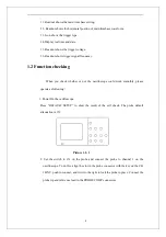
11. Readout shows the main time base setting.
12.
Readout shows the horizontal positon of main timebase waveform.
13. Icon shows the trigger type.
14.Display real time and date.
15. Readout shows the trigger voltage.
16. Readout shows trigger signal frequency.
1.2 Function checking
When you check whether or not the oscilloscope could work smoothly, please
operate as following:
1. Power On the oscilloscope.
Press “DEFAULT SETUP” to show the result of the self check. The probe default
attenuation is 1X.
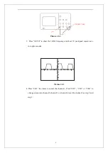
Picture 1.2- 1
2. Set the switch to 1X on the probe and connect the probe to channel 1 on the
oscilloscope. To do this, align the slot in the probe connector with the key on the CH
1 BNC, push to connect, and twist to the right to lock the probe in place. Connect the
probe tip and reference lead to the PROBE COMP connectors
Summary of Contents for SDS1000 Series
Page 146: ...138 Coupling DC...

