23
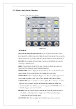
Setting up CH1,CH2,CH3,CH4 Channels
Each channel has its own separate Menu. The items are set up separately
according to each channel.
1. Choosing Coupling
Take the CH1 for example; the tested signal is a sine wave signal with DC
deflection:
●
Press“CH1”
→
“Coupling”
→
“AC”, Set to AC couple mode. It blocks the DC
component of the input signal.
●
Press“CH1”
→
“Coupling”
→
“DC”, Set to DC couple mode. Both
DC and AC component could be obstructed.
●
Press“CH1”
→
“Coupling”
→
“GND”, Set to GROUND mode. It disconnects the
input signal.
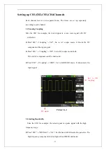
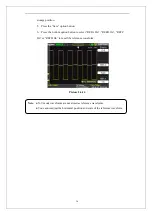
Picture 2.6-2
2. Limiting Bandwidth
Take the CH1 for example; the tested signal is a pulse signal with the high
frequency surge:
●
Press “CH1”
→
“BW Limit”
→
“On”
,
Set the band width Limited to open state. The
high frequency component which is higher than 20MHz obstructed.
Set to DC
coupling
DC status
Summary of Contents for SDS1000 Series
Page 146: ...138 Coupling DC...

