70
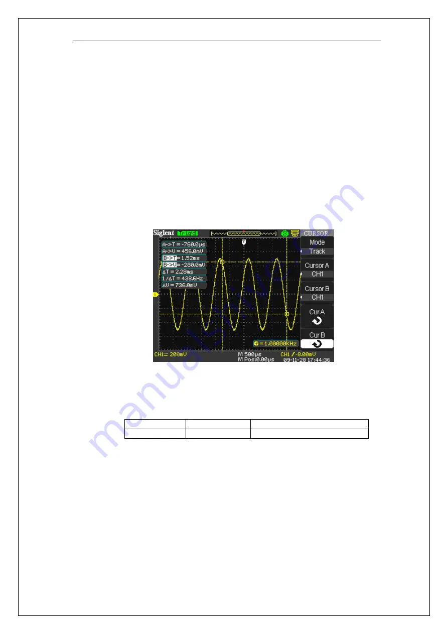
B
→
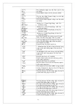
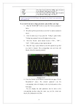
T: The horizontal position of Cursor B (Time cursor centered around the
midpoint of screen).
B
→
V: The Vertical position of Cursor B (Voltage cursor centered around
channel ground level).
△
T: Horizontal space between Cursor A and Cursor B (Time value between two
cursors).
1/
△
T: The reciprocal of horizontal space between cursor A and cursor B.
△
V: Vertical space between Cursor A and Cursor B (Voltage value between two
cursors).
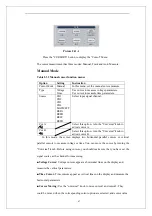
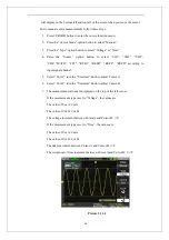
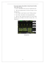
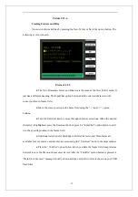
Picture 2.11-3
Auto mode
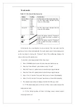
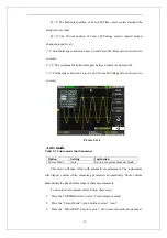
Table 2-34 Auto mode function menu:
Option Setting Instruction
Cursor Mode
Auto
Set to auto cursor measure mode.
This mode will take effect with automatic measurements. The instruments
will display cursors while measuring parameters automatically. These cursors
demonstrate the physical meanings of these measurements.
To do auto cursor measurements, follow these steps:
1.
Press the CURSOR button to enter “Cursor measure menu”.
2.
Press the “Cursor Mode” option button to select “Auto”.
3.
Press the “MEASURE” button to enter “Auto cursor measure mode menu”
Summary of Contents for SDS1000 Series
Page 146: ...138 Coupling DC...

