SIGLENT
SDS1000CFL Service Manual 23
To verify Bandwidth
This test checks the bandwidth of all input channels. In the test, both the
impedance of FLUKE and the oscilloscope are required to set to 50Ω, we could
complete that for FLUKE by easy operation on the front panel. But for the
oscilloscope, it proves to be a little different. As described in chapter 1, the
SDS1000CFL series oscilloscope has four different Bandwidths, and only two
kinds of them are designed with 50Ω impedance selectable.
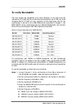
Table 3-3 Input Impedance for SDS1000CFL
Model
Channels
Bandwidth
Input Impedance
SDS1072CFL
2
70MHz
Not set
SDS1074CFL
4
70MHz
Not set
SDS1102CFL
2
100MHz
Not set
SDS1104CFL
4
100MHz
Not set
SDS1202CFL
2
200MHz
50
Ω
/1M
Ω
SDS1204CFL
4
200MHz
50
Ω
/1M
Ω
SDS1302CFL
2
300MHz
50
Ω
/1M
Ω
SDS1304CFL
4
300MHz
50
Ω
/1M
Ω
For oscilloscope with 70MHz or 100MHz bandwidth, the 50Ω feedthrough
terminator need to be added to the end of BNC cable connected to FLUKE
9500B. In addition, for oscilloscope with 200MHz or 300MHz bandwidth, you
could also add the 50Ω feedthrough terminator by setting the Input Impedance
to 1MΩ.
To test the bandwidth at 200mV/div and 100mV/div
Steps:
1. Connect channel 1 of the oscilloscope to Sine Wave Generator of
FLUKE 9500B via the BNC cable and probe specified for it.
2. Set the oscilloscope Volt/Div to 200mV/div, the Sec/Div to 50mS/div.
3. Set the frequency of 9500B to 10Hz.
4. Set the amplitude of 9500B to 3v.
5. Press the MEASURE button on the front panel of the oscilloscope to
display V
pp
measurement.
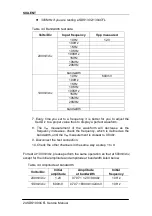
6. Set the frequency of 9500B to:
70MHz if you are testing a SDS1072/1074CFL
100MHz if you are testing a SDS1102/1104CFL
200MHz if you are testing a SDS1202/1204CFL

