SIG
L
ENT
SDS2000X-E User Manual
113
FFT Operation
FFT is used to compute the fast Fourier transform using analog input channels. AnFFT
takes the digitized time record of the specified source and transforms it to the frequency
domain. This can be useful when you wish to observe the frequency content of a time
varying signal, such as Electromagnetic Interference or RF transmission applications.
When the FFT function is selected, the FFT spectrum is plotted on the oscilloscope
display as magnitude in dBV versus frequency. The readout for the horizontal axis
changes from time to frequency (Hertz) and the vertical readout changes from Volts to dB.
FFT operation can facilitate the following works:
Measure harmonic components and distortion in the device under test
Measure the characteristics of the noise in DC power
Analyze vibration
To display a FFT waveform:
1. Press the
Math
button on the front panel to open the MATH function menu.
2. Press the
Operator
softkey and then turn the
Universal Knob
to select
FFT
. The
resulting math waveform is displayed in white and labeled with an “M” icon.
3. Press the
Source
softkey, and then turn the
Universal Knob
to select the source to
do FFT operation. Analog channels can be used as the source.
4. Press the
Window
softkey, and then turn the
Universal Knob
to select an appropriate
window.
Spectral leakage can be considerably decreased when a window function is used. The
oscilloscope provides five windows (Rectangle, Blackman, Hanning, Hamming and
Flattop) which have different characteristics and are applicable to measure different
waveforms. You need to select the window function according to different waveforms
and their characteristics. Please read the table below carefully to make an appropriate
option according to the input signal.
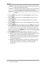
Window
Applications and Characteristics
Rectangle
Normally used when the signal is transient (completely contained in
the time-domain window) or known to have a fundamental frequency
component that is an integer multiple of the fundamental frequency
of the window. Signals other than these types will show varying
amounts of spectral leakage and scallop loss, which can be
corrected by selecting another type of window
Hanning
These reduce leakage and improve amplitude accuracy. However,
frequency resolution is also reduced.
Summary of Contents for SDS2000X-E Series
Page 1: ...User Manual SDS2000X E Series Digital Oscilloscope UM0102E E01A SIGLENT TECHNOLOGIES CO LTD...
Page 14: ......
Page 69: ...SIGLENT SDS2000X E User Manual 43 Figure 13 x Interpolation Figure 14 Sin x x Interpolation...
Page 98: ...SIGLENT 72 SDS2000X E User Manual Figure 29 Relative Window Trigger...
Page 100: ...SIGLENT 74 SDS2000X E User Manual Figure 30 Interval Trigger...
Page 103: ...SIGLENT SDS2000X E User Manual 77 Figure 32 State Dropout Trigger...
Page 105: ...SIGLENT SDS2000X E User Manual 79 Figure 33 Runt Trigger...
Page 125: ...SIGLENT SDS2000X E User Manual 99 Figure 49 CAN Trigger...
Page 129: ...SIGLENT SDS2000X E User Manual 103 Figure 51 LIN Trigger...
Page 162: ...SIGLENT 136 SDS2000X E User Manual...
Page 200: ...SIGLENT 174 SDS2000X E User Manual Figure 95 Built in Arb interface...
Page 206: ...SIGLENT 180 SDS2000X E User Manual Figure 100 WiFi setting menu...
Page 215: ...SIGLENT SDS2000X E User Manual 189 Figure 108 Option Information...


