SIG
L
ENT
SDS2000X-E User Manual
119
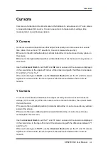
Cursors
Cursors are horizontal and vertical markers that indicate X- axis values and Y- axis values
on a selected waveform source. You can use cursors to make custom voltage, time
measurements on oscilloscope signals.
X Cursors
X cursors are vertical dashed lines that adjust horizontally and can be used to measure
time (when the source is FFT waveform, X cursors measure frequency)
X1
cursor is the left (default position) vertical dotted line; it can be moved to any place on
the screen.
X2
cursor is the right (default position) vertical dotted line; it can be moved to any place on
the screen.
Use the
Universal Knob
to set the
X1
and
X2
cursor values and the values are displayed
in the cursors box in the upper-left corner of the screen along with the difference between
X1 and X2 (
△
T) and 1/
△
T.
When set cursor type to
X2-X1
, use the
Universal Knob
will move the X1 and X2 cursors
together. The value under the menu option is the difference between the X1 and X2
cursors.
Y Cursors
Y cursors are horizontal dotted lines that adjust vertically and can be used to measure
voltage (V) or current (A). When the cursor source is the math function, the unit will match
the math function.
Y1
cursor is the top (default position) horizontal dotted line; it can be moved to any vertical
place of the screen.
Y2
cursor is the down (default position) horizontal dotted line; it can be moved to any
vertical place of the screen.
Use the
Universal Knob
to set the Y1 and Y2 cursor values and the values are displayed
in the cursors box in the top left corner of the screen along with the difference between Y1
and Y2 (
△
Y).
When set cursor type to
Y2-Y1
, use the
Universal Knob
will move the Y1 and Y2 cursors
together. The value under the menu option is the difference between the Y1 and Y2
cursors.
Summary of Contents for SDS2000X-E Series
Page 1: ...User Manual SDS2000X E Series Digital Oscilloscope UM0102E E01A SIGLENT TECHNOLOGIES CO LTD...
Page 14: ......
Page 69: ...SIGLENT SDS2000X E User Manual 43 Figure 13 x Interpolation Figure 14 Sin x x Interpolation...
Page 98: ...SIGLENT 72 SDS2000X E User Manual Figure 29 Relative Window Trigger...
Page 100: ...SIGLENT 74 SDS2000X E User Manual Figure 30 Interval Trigger...
Page 103: ...SIGLENT SDS2000X E User Manual 77 Figure 32 State Dropout Trigger...
Page 105: ...SIGLENT SDS2000X E User Manual 79 Figure 33 Runt Trigger...
Page 125: ...SIGLENT SDS2000X E User Manual 99 Figure 49 CAN Trigger...
Page 129: ...SIGLENT SDS2000X E User Manual 103 Figure 51 LIN Trigger...
Page 162: ...SIGLENT 136 SDS2000X E User Manual...
Page 200: ...SIGLENT 174 SDS2000X E User Manual Figure 95 Built in Arb interface...
Page 206: ...SIGLENT 180 SDS2000X E User Manual Figure 100 WiFi setting menu...
Page 215: ...SIGLENT SDS2000X E User Manual 189 Figure 108 Option Information...


