background image

SIG

L

ENT 

176

    SDS2000X-E 

User Manual


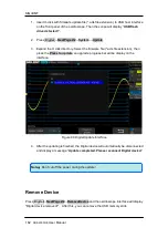
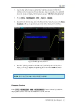
b)  Adjust the voltage of channel 2 channel to 1 mV/div, and make the waveform 

visible in the oscilloscope interface, press the 

Measure

 and measure the mean 

value of channel 2. 

c)  Press the 

Manual

 and rotate the knob to adjust the waveform, so that the mean 

value of the observed CH2 will be in the range of ± 1 mV, and then press the 

Save

.


Upon completion of the zero adjust process, the oscilloscope will  display " 

Zero Adjust Completed! ". 


Systems 

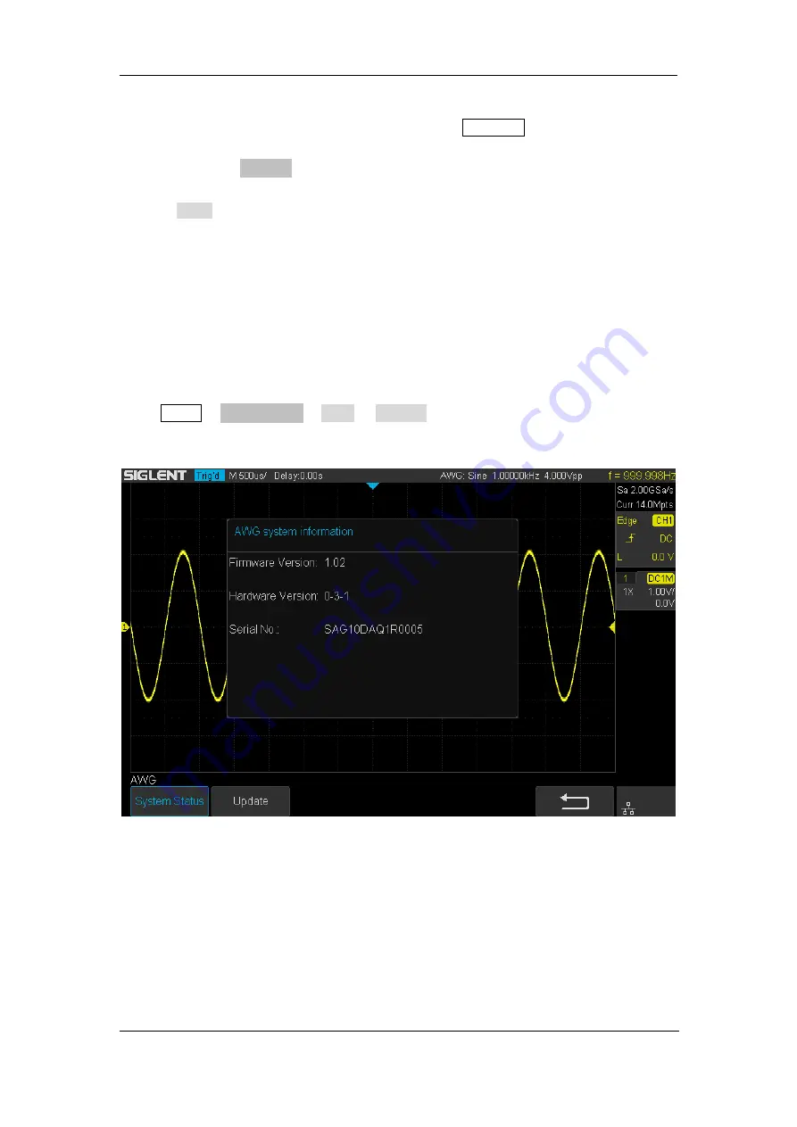
1.  System Status 

 
Press 

Utility

 →

NextPage4/4

→ 

AWG

 → 

System

 , then select the System Status option to 

view  the  AWG’s  system  information,  including  software  version,  hardware  version,  and 
serial number. After finished, press the return soft key to exit the system information page.   


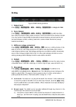
Figure 97 AWG System Information Interface 


2.  Update 


The software version file of the AWG can be updated directly via U-disk. Follow the steps 
below: 


Summary of Contents for SDS2000X-E Series

Page 1: ...User Manual SDS2000X E Series Digital Oscilloscope UM0102E E01A SIGLENT TECHNOLOGIES CO LTD...

Page 2: ...cation replaces all previously corresponding material Any way of copying extracting or translating the contents of this manual is not allowed without the permission of SIGLENT Product Certification SI...

Page 3: ...ore connecting the instrument please read the manual carefully to gain more information about important ratings Use Proper Overvoltage Protection Make sure that no overvoltage such as that caused by a...

Page 4: ...nfluence of dust and or moisture in air please keep the surface of the device clean and dry Handling Safety Please handle with care during transportation to avoid damaging buttons knob interfaces and...

Page 5: ...Terms on the product These terms may appear on the product DANGER Indicates direct injuries or hazards that may happen WARNING Indicates potential injuries or hazards that may happen CAUTION Indicates...

Page 6: ...directly connected to the low voltage installation Examples are measurements on household appliances portable tools and similar equipment Measurement category III is for measurements performed in the...

Page 7: ...forming to installation overvoltage category II WARNING Make sure that no overvoltage such as that caused by thunder lightning can reach the product or else the operator might expose to danger of elec...

Page 8: ...tions and have free air When using the oscilloscope in a bench top or rack setting provide at least 10 cm clearance beside above and behind the instrument for adequate ventilation WARNING Inadequate v...

Page 9: ...clean the instrument and probe 1 Disconnect the instrument from all power sources and then clean it with a soft wet cloth 2 Clean the loose dust on the outside of the instrument and probe with a soft...

Page 10: ...toutes les estimations et instruction de signe de l instrument Avant de relier l instrument lisez svp le manuel soigneusement pour obtenir plus d informations sur les estimations Employez la protecti...

Page 11: ...idit en air maintenez svp la surface du dispositif propre et s che En manipulant la s ret manipulez svp avec soin pendant le transport pour viter d endommager des boutons des interfaces de bouton et d...

Page 12: ...e propri t Limites sur le produit Ces limites peuvent appara tre sur le produit Le DANGER indique les dommages ou les risques directs qui peuvent se produire Dommages ou risques potentiels de WARNINGI...

Page 13: ...cuits directement reli s l installation de basse tension Les exemples sont des mesures sur des appareils lectrom nagers des outils portatifs et l quipement semblable La cat gorie III de mesure est pou...

Page 14: ......

Page 15: ...e non fonctionnement moins de 15 kilom tres La cat gorie d installation surtension ce produit est actionn e par des forces conform ment la cat gorie II d installation surtension EN AVERTISSANT assurez...

Page 16: ...t de support fournissezau moins le d gagement de 10 centim tres pr s au dessus et derri re de l instrument pour ventilation proportionn e La ventilation insatisfaisante peut causer l augmentation de l...

Page 17: ...affichage cristaux liquides salut pour viter de le scarifier Pour viter d endommager la surface de l instrument svp n utilisez aucune pierreuse corrosive de liquide ou de produit chimique Assurez vou...

Page 18: ...Waveform Introduce how to save and display REF waveform Math Introduce the math operation function of the oscilloscope Cursors Introduce how to use cursors to make measurements Measure Introduce how...

Page 19: ...nnement I Condition de ventilation II Soin g n ral et nettoyage II Document Overview IV Quick Start 1 General Inspection 2 Appearance and Dimensions 3 Prepare for Using 4 Adjust the Supporting Legs 4...

Page 20: ...36 Overview 37 Sampling Theory 37 Sample Rate 37 Bandwidth and Sample Rate 38 Memory Depth 40 Sampling Mode 41 Interpolation Method 42 Acquisition Mode 44 Normal 44 Peak Detect 44 Average 46 Eres 47 H...

Page 21: ...ode 97 Setup for CAN Signals 97 CAN Trigger 98 CAN Serial Decode 100 LIN Trigger and Serial Decode 101 Setup for LIN Signals 101 LIN Trigger 102 LIN Serial Decode 104 Reference Waveform 106 Save REF W...

Page 22: ...Grid Type 143 Intensity 143 Grid Brightness 144 Transparence 144 Save and Recall 145 Save Type 146 Internal Save and Recall 148 External Save and Recall 149 Disk Management 152 Create a New File or Fo...

Page 23: ...169 Arbitrary Waveform Generator Option 171 Output 172 Wave 172 Setting 175 Systems 176 Remove Device 177 IO Set 178 USB Device 178 LAN 178 WLAN Option 179 Web Server 181 Update Firmware and Configur...

Page 24: ...Mode 45 Figure 18 With Random Noise Normal Mode 46 Figure 19 With Random Noise Average Mode 47 Figure 20 SEQUENCE Function Menu 50 Figure 21 HISTORY Function Menu 50 Figure 22 Turn off the Noise Reje...

Page 25: ...Figure 61 Measure Pulse Width 120 Figure 62 Voltage Measurements 122 Figure 63 Overshoot 123 Figure 64 Preshoot 123 Figure 65 Time Measurements 124 Figure 66 Select the Measurement Parameter 126 Figu...

Page 26: ...face 175 Figure 97 AWG System Information Interface 176 Figure 99 AWG Update Interface 177 Figure 100 LAN Setting Interface 179 Figure 101 WIFI setting Interface 180 Figure 102 web server interface 18...

Page 27: ...he oscilloscope for the first time the front panel rear panel and user interface of the oscilloscope The contents of this chapter General Inspection Appearance and Dimensions Prepare for Using Front P...

Page 28: ...chanical tests The consigner or carrier shall be liable for the damage to instrument resulting from shipment SIGLENT is not responsible for free maintenance rework or replacement of the unit 2 Inspect...

Page 29: ...SIGLENT SDS2000X E User Manual 3 Appearance and Dimensions Figure 1 Front View Figure 2 Top View...

Page 30: ...Using Adjust the SupportingLegs Adjust the supporting legs properly to use them as stands to tilt the oscilloscope upwards for stable placement of the oscilloscope as well as better operation and obs...

Page 31: ...ress the power key at the lower left corner of the front panel to start the oscilloscope During the start up process the oscilloscope performs a series of self tests and you can hear the sound of rela...

Page 32: ...al of the probe 4 Press the Auto Setup 5 Observe the waveform on the display In normal operating conditions the display should be a square waveform as shown in the figure below Figure 5 Functional Ins...

Page 33: ...naccuracy or error The probe compensation procedures are as follows 1 Perform steps 1 2 3 and 4 of Function Inspection in the previous section 2 Check the waveforms displayed and compare them with the...

Page 34: ...Universal Knob 13 Trigger Control 3 Common Function Menus 14 Menu on off 4 Clear Sweeps 15 Menu Softkey 5 Run Stop 16 One Button shortcut for Save 6 Decode 17 Analog Channel 7 Auto Setup 18 Power Butt...

Page 35: ...ntrol the oscilloscope through this interface 4 USB Host Communicate with external function generators SIGLENT SDG and SAG1021 5 Safety Lock Hole You can lock the instrument to a fixed location using...

Page 36: ...en you turn the knob During the modification waveforms of all the channels would move left or right and the trigger position message at the upper right corner of the screen would change accordingly Pr...

Page 37: ...Variable Knob Adjust the vertical scale of the current channel Turn clockwise to decrease the scale and turn counterclockwise to increase During the modification the amplitude of the waveform should...

Page 38: ...e to Normal Press the button to set the trigger mode to Single Trigger Level Knob Adjust the trigger level Turn clockwise to increase the level and turn counterclockwise to reduce the level During mod...

Page 39: ...scale horizontal time base and trigger mode according to the input signal to help configure the instrument to display some waveform information The oscilloscope may have difficulty showing slow signa...

Page 40: ...he intensity and counterclockwise to reduce In addition it can also be used to adjust scale and offset of MATH and REF Press this button to display the virtual menu you can directly select the desired...

Page 41: ...to clear the count and recount it When persist is enabled press the button to clear persist Press to enter the MEASURE function menu to set the measurement parameters all measurement statistics and s...

Page 42: ...the most you can set is 80000 Press to enter the DECODE function menu The oscilloscope supports I2C SPI UART CAN and LIN serial bus decode Press to turn off on the navigate function SDS2000X E support...

Page 43: ...function that supplies multi language help information You can access the help function by pressing any button for 2 seconds and a help window will open with a brief explaination of the selected funct...

Page 44: ...lor of the channel 3 Trigger Status Available trigger status includes Ready Auto Stop Arm Trig d 4 Horizontal Time Base Represent the time per grid on the horizontal axis on the screen Use the Horizon...

Page 45: ...tup Probe attenuation factor Display the current probe attenuation factor of the channel Available probe attenuation factors 0 1X 0 2X 0 5X 1X properties 2000X 5000X 10000X Custom A Custom B Custom C...

Page 46: ...e security lock not included to lock the oscilloscope to a fixed location The method is as follows align the lock with the lock hole and plug it into the lock hole vertically turn the key clockwise to...

Page 47: ...tem This chapter introduces how to set the vertical system of the oscilloscope The contents of this chapter Enable the Channel Vertical Scale Vertical Position Coupling Bandwidth Limit Probe Input Imp...

Page 48: ...d at the bottom of the screen and the channel label at the right side of the screen The information displayed in the channel label is related to the current channel setting After the channel is turned...

Page 49: ...bit lower if the next scale is used fine adjustment can be used to improve the amplitude of waveform display to view signal details Press the CH1 button on the front panel then press the Adjust softk...

Page 50: ...cal position information Volts Pos displays at the bottom of the screen The table below shows the range of vertical position according to the volt scale Volt Scale Range of Vertical Position 500 V div...

Page 51: ...g mode The default setup is DC The current coupling mode is displayed in the channel label at the right side of the screen You can also press the Coupling softkey continuously to switch the coupling m...

Page 52: ...the probe attenuation factor Menu Attenuation Factor 0 1X 0 1 1 0 2X 0 2 1 0 5X 0 5 1 1X 1 1 2X 2 1 5000X 5000 1 10000X 10000 1 Custom 1000000 1 0 000001 1 You can also press the Probe softkey select...

Page 53: ...have different cable lengths or other causes of time skew between channels The valid deskew range of each analog channel is 100 ns 1 Press CH1 button on the front panel to enter the CH1 function menu...

Page 54: ...ther the current channel waveform is visible 1 Press CH1 button on the front panel to enter the CH1 function menu 2 Press the Next Page softkey to enter the second page of the CH1 function menu 3 Pres...

Page 55: ...SIGLENT SDS2000X E User Manual 29 Horizontal System This chapter introduces how to set the horizontal system of the oscilloscope The contents of this chapter Horizontal Scale Trigger Delay Roll Zoom...

Page 56: ...e information at the upper left corner of the screen will change accordingly during the adjustment The range of the horizontal scale is from 500 ps div to 100 s div The Horizontal Scale Knob works in...

Page 57: ...and indicates how far it is from the time reference point These reference points are indicated along the top of the display grid All events displayed left of the trigger point happened before the tri...

Page 58: ...he current time base setting is faster than the 50 ms div limit it will be set to 50 ms div when Roll mode is entered If you would like to stop the display in Roll mode press the Run Stop button To cl...

Page 59: ...a of the normal display that is expanded is outlined with a box and the rest of the normal display shows aghosted background The boxshows the portion of the normal sweep that is expanded in the lower...

Page 60: ...SIGLENT 34 SDS2000X E User Manual To change the time base of the normal window turn off Zoom then turn the Horizontal Scale Knob...

Page 61: ...This chapter introduces how to use the run control and set the sampling system of the oscilloscope The contents of this chapter Run Control Overview Memory Depth Sampling Mode Interpolation Method Ac...

Page 62: ...e and display a single acquisition whether the oscilloscope is running or stopped press Single The Single run control lets you view single shot events without subsequent waveform data overwriting the...

Page 63: ...mum sample rate of the oscilloscope is 2 GSa s The actual sample rate of the oscilloscope is determined by the horizontal scale and memory depth Turn the Horizontal Scale Knob to adjust the sample rat...

Page 64: ...nd Sample Rate An oscilloscope s bandwidth is typically described as the lowest frequency at which input signal sine waves are attenuated by 3 dB 30 amplitude error At the oscilloscope bandwidth sampl...

Page 65: ...he fundamental frequency and an infinite number of odd harmonics and typically for 500 MHz bandwidths and below oscilloscopes have a Gaussian frequency response So in practice an oscilloscope s sample...

Page 66: ...rsal Knob to select the desired value and push down the knob to confirm Press the Mem Depth softkey continually can also select the desired value The actual memory depth is displayed in the informatio...

Page 67: ...the oscilloscope samples and displays waveform within a trigger event The maximum real time sample rate is 2 GSa s Press the Run Stop button to stop the sample the oscilloscope will hold the last disp...

Page 68: ...the gaps between points Press the Acquire button on the front panel to enter the ACQUIRE Function menu then press the Interpolation softkey to select Sinx x or X X The adjacent sample points are dire...

Page 69: ...SIGLENT SDS2000X E User Manual 43 Figure 13 x Interpolation Figure 14 Sin x x Interpolation...

Page 70: ...ed acquisition mode and push down the knob to confirm The default setup is Normal Normal In this mode the oscilloscope samples the signal at equal time intervals to rebuild the waveform For most of th...

Page 71: ...5 displayed would be larger In this mode the oscilloscope can display all the pulses with pulse widths at least as wide as the sample period Figure 16 Pulse With 0 01 Duty Normal Mode Figure 17 Pulse...

Page 72: ...f averages is the lower the noise will be and the higher the vertical resolution will be but the slower the response of the displayed waveform to the waveform changes will be The available range of av...

Page 73: ...This is generally used when the sample rate of the digital converter is higher than the storage rate of the acquisition memory Eres mode can be used on both single shot and repetitive signals and it...

Page 74: ...requency and phase relationships between two signals XY mode can also be used with transducers to display strain versus displacement flow versus pressure volts versus current or voltage versus frequen...

Page 75: ...ual 49 X Y function can be used to measure the phase deviation occurred when the signal under test passes through a circuit network Connect the oscilloscope to the circuit to monitor the input and out...

Page 76: ...buffer has been filled it then displays the waveforms on the screen To use the sequence mode the Horizontal Format must be set to YT Do the following steps to use the sequence mode 1 Press the Acquire...

Page 77: ...and shows the frame number that displaying on the screen 3 Press the Frame No softkey and then turn the Universal Knob to select the frame to display 4 Press the softkey to replay the waveform from th...

Page 78: ...rms acquired overlap to display stable waveform The following is the schematic diagram of the acquisition memory As shown in the figure below the position of the trigger event is determined by the ref...

Page 79: ...E User Manual 53 Trigger Level Trigger Coupling Holdoff Noise Rejection Trigger Type Edge Trigger Slope Trigger Pulse Trigger Video Trigger Window Trigger Interval trigger Dropout Trigger Runt Trigger...

Page 80: ...G channel when the oscilloscope collects data simultaneously on multiple analog channels The trigger signal such as an external clock signal of the circuit to be tested should be connected to EXT and...

Page 81: ...g if the specified trigger conditions are not found triggers are forced and acquisitions are made so that signal activity is displayed on the oscilloscope The waveforms may not be stable on the displa...

Page 82: ...er Level Knob to set the level to the waveform s 50 value immediately If AC coupling is used pushing the Trigger Level knob sets the trigger level to about 0 V The position of the trigger level for th...

Page 83: ...components into the trigger path AC Block all the DC components and attenuate signals lower than 8 Hz Use AC coupling to get a stable edge trigger when your waveform has a large DC offset LF Reject B...

Page 84: ...example to get a stable trigger on the repetitive pulse burst shown below set the holdoff time to be 200 ns but 600 ns The correct holdoff setting is typically slightly less than one repetition of the...

Page 85: ...he possibility of triggering on noise However this also decreases the trigger sensitivity so that a slightly larger signal is required to trigger the oscilloscope Press the Setup button on the front p...

Page 86: ...orm First stabilize the displayed waveform by removing the noise from the trigger path Second reduce the noise on the displayed waveform 1 Connect a signal to the oscilloscope and obtain a stable disp...

Page 87: ...er Type The oscilloscope provides abundant advanced trigger functions including various serial bus triggers Edge trigger Slope trigger Pulse trigger Video trigger Window trigger Interval trigger Dropo...

Page 88: ...Press the Type softkey turn the Universal Knob to select Edge and then push the knob to confirm 3 Press the Source softkey turn the Universal Knob to select the deserted trigger source 4 Press the Slo...

Page 89: ...n push the knob to confirm 3 Press the Source softkey turn the Universal Knob to select CH1 or CH2 as the trigger source 4 Press the Slope softkey turn the Universal Knob to set select the desired tri...

Page 90: ...an a time value Trigger when the positive or negative slope time of the input signal is greater than the specified time value within a range of time value Trigger when the positive or negative slope t...

Page 91: ...key to select Positive or Negative pulse that to trigger on The current trigger polarity is displayed at the upper right corner of the screen 6 Press the Limit Range softkey turn the Universal Knob to...

Page 92: ...than the specified upper limit of the set time value For example for a positive pulse if you set t pulse real width 100 ns and t 300 ns the waveform will trigger outside a range of time value Trigger...

Page 93: ...softkey turn the Universal Knob to select CH1 or CH2 as the trigger source Turn the Trigger Level Knob does not change the trigger level because the trigger level is automatically set to the sync pul...

Page 94: ...50 HDTV 1080i 60 1 to 562 1 to 563 The following are exercises to familiarize you with video triggering To trigger on a specific line of video To use custom video trigger To Trigger on a Specific Line...

Page 95: ...H1 as the trigger source and push down the knob to confirm 4 Press the Standard softkey turn the UniversalKnob to select Custom and push down the knob to confirm 5 Press the Setting softkey to enter t...

Page 96: ...while the lower trigger level is out of the waveform amplitude range the oscilloscope will trigger on rising edge only If the lower trigger level is within the waveform amplitude range while the upper...

Page 97: ...turn the Universal Knob to select CH1 or CH2 as the trigger source 4 Press the Window Type softkey to select Relative 5 Press the Center Delta softkey to select Center or Delta trigger level mode the...

Page 98: ...SIGLENT 72 SDS2000X E User Manual Figure 29 Relative Window Trigger...

Page 99: ...elect desired condition less than a time value Trigger when the positive or negative pulse time of the input signal is lower than the specified time value greater than a time value Trigger when the po...

Page 100: ...SIGLENT 74 SDS2000X E User Manual Figure 30 Interval Trigger...

Page 101: ...ising edge passes through the trigger level is greater than the timeout time set as shown in the figure below To set edge Dropout trigger 1 Press the Setup button on the front panel to enter the TRIGG...

Page 102: ...Type softkey then turn the UniversalKnob to select Dropout and push down the knob to confirm 3 Press the Source softkey turn the Universal Knob to select CH1 or CH2 as the trigger source 4 Press the S...

Page 103: ...SIGLENT SDS2000X E User Manual 77 Figure 32 State Dropout Trigger...

Page 104: ...key then turn the UniversalKnob to select Runt and push down the knob to confirm 3 Press the Source softkey turn the Universal Knob to select CH1 or CH2 as the trigger source 4 Press the Polarity soft...

Page 105: ...SIGLENT SDS2000X E User Manual 79 Figure 33 Runt Trigger...

Page 106: ...to confirm 3 Press each channel softkey to select Invalid High or Low Low sets the pattern to low on the selected channel A low is a voltage level that is less than the channel s trigger level or thre...

Page 107: ...SIGLENT SDS2000X E User Manual 81 7 Press the Holdoff Close softkey to turn on the Holdoff function then turn the Universal Knob to select the desired value Figure 34 Pattern Trigger...

Page 108: ...d LIN serial trigger and decode This chapter introduces the method of triggering and decoding these serial signals in detail The contents of this chapter I2C Trigger and Serial Decode SPI Trigger and...

Page 109: ...SIGNAL Menu 5 Set SCL I2C s clock signal a Press SCL softkey to select the channel that is connected to the I2C clock signal b Press first Threshold softkey to set the I2C clock signal s threshold vol...

Page 110: ...The oscilloscope will be triggered when another Start condition occurs before a Stop condition No Ack The oscilloscope will be triggered when SDA data is high during any SCL s ACK bit EEPROM The trig...

Page 111: ...y data value will be matched 10 Address Data The oscilloscope will be triggered when the following conditions are satisfied The address s length must be 10 bits and the address s value is the same as...

Page 112: ...to set the qualifier or b Press Data1 softkey and set its value by turning the Universal Knob If you select 7 Addr Data or 10 Addr Data condition a Press the Addr softkey and turn the Universal Knob...

Page 113: ...d set the number of lines by Universal Knob The range of the lines is 1 to 7 6 Press Format to change the character encoding format of the decoding s result 7 Press Scroll and turn the Universal Knob...

Page 114: ...ss Signal softkey to enter the SIGNAL menu as Figure 38 shows Figure 38 SPI SIGNAL Menu 5 Set CLK clock signal a Press the CLK softkey to enter CLK menu b Press the CLK softkey to select the channel t...

Page 115: ...e trigger voltage level when the trigger type is set to serial d Press softkey to return previous menu Figure 41 MOSI Menu 8 Set CS a Press the CS softkey to enter the MOSI menu b Press the CS Type so...

Page 116: ...lave In Table 2 Menu Explanations of the SPI trigger type 6 Press the Data Length softkey and turn the Universal Knob to set the length of a data The range of data length is 4 to 96 bits 7 Set the val...

Page 117: ...Lines and set the number of lines by Universal Knob The range of the lines is 1 to 7 6 Press Format to change the character encoding format of the decoder s result 7 Press Scroll and turn the Univers...

Page 118: ...ger voltage level when the trigger type is set to serial 6 Set TX a Press TX to select the channel that is connected to the TX signal b Press first Threshold key to set the TX signal s threshold volta...

Page 119: ...SIGLENT SDS2000X E User Manual 93 13 Press Next Page softkey 14 Press the Bit Order softkey to select the bit order LSB or MSB 15 Press Idle Level softkey to set the idle level Low or High...

Page 120: ...the Condition softkey and set up the desired trigger condition Start The oscilloscope will be triggered at the position of the start bit Stop The oscilloscope will be triggered at the position of the...

Page 121: ...ss Display and choose the same options as the first step 5 Press Lines and set the number of lines by Universal Knob The range of the lines is 1 to 7 6 Press Format to change the character encoding fo...

Page 122: ...96 SDS2000X E User Manual position RX The receiving channel TX The transmitting channel RX Err Parity error or unknown error in the data received TX Err Parity error or unknown error in the data tran...

Page 123: ...NAL menu as Figure 48 shows Figure 48 CAN SIGNAL Menu a Press Source softkey to select the channel that is connected to the CAN signal b Press Threshold key to set the CAN signal s threshold voltage l...

Page 124: ...nu 5 Press Condition and select the trigger condition by Universal Knob If you select the Remote and ID condition a Press ID Bits to set the length of the ID 11 or 29 bits b Press Curr ID Byte and use...

Page 125: ...SIGLENT SDS2000X E User Manual 99 Figure 49 CAN Trigger...

Page 126: ...ding format of the decoder s result 7 Press Scroll and turn the Universal Knob to viewall frames Interpreting CAN Decode The frame of decoding result The Arbitration field is displayed in frame The Co...

Page 127: ...N by turning UniversalKnob 4 Press Signal softkey to enter the SIGNAL menu as Figure 50 shows Figure 50 LIN SIGNAL Menu 5 Press Source softkey to select the channel that is connected to the LIN signal...

Page 128: ...ignal has a data is the same as that value If you have set both Data1 s and Data2 s value the signal should has two consecutive data the first data s value is Data1 second data value is Data2 Note If...

Page 129: ...SIGLENT SDS2000X E User Manual 103 Figure 51 LIN Trigger...

Page 130: ...T function menu 4 Press Display and choose the same options as the first step 5 Press Lines and set the number of lines by Universal Knob The range of the lines is 1 to 7 6 Press Format to change the...

Page 131: ...displacement between the current frame and trigger position ID The value of the frame s protected identifier field Data Length The length of the data field ID Parity The two check bits of the protecte...

Page 132: ...e reference waveform locations in the oscilloscope Then a reference waveform can be displayed and compared against other waveforms All reference waveforms can be displayed at one time The contents of...

Page 133: ...annel The source includes analog channel and math waveforms 3 Press the Location softkey then turn the Universal Knob to select the position to save the REF waveform The source includes analog channel...

Page 134: ...ob to adjust the vertical scale and position of the reference waveform The vertical scale and position information display at the middle of the screen The initial values display at the middle of the s...

Page 135: ...be cut off Math The oscilloscope supports many math operations between analog channels including addition subtraction multiplication division FFT differential d dt integral dt square root The resulti...

Page 136: ...channel to V or A The oscilloscope math operation includes units as below Math Operation Unit Addition or subtraction V A or U multiplication V 2 A 2 or W Volt Amp division None Sie or FFT dBVrms Vrms...

Page 137: ...point by point and the result is displayed 1 Press the Math button on the front panel to enter the MATH function menu 2 Press the Source A and Source B softkey respectively and then turn the Universal...

Page 138: ...menu 2 Press the Source A and Source B softkey respectively and then turn the Universal Knob to select the source to do math operation The device supports multiplication and division between analog c...

Page 139: ...yed in white and labeled with an M icon 3 Press the Source softkey and then turn the Universal Knob to select the source to do FFT operation Analog channels can be used as the source 4 Press the Windo...

Page 140: ...tkey to select the unit of vertical axis The units of the vertical axis can be dBVrms dBm or Vrms which use a logarithmic scale or a linear scale to display vertical amplitude respectively If you need...

Page 141: ...Press the AUTO SET softkey to automatically set the appropriate parameters for the FFT measurement 12 Press the Display softkey and select Normal Maximum Hold and Average to display the FFT waveform...

Page 142: ...s i data point index t point to point time difference The dx option under d dt math function operation menu shows the point to point time difference and it ranges from 0 02div to 0 40div div indicates...

Page 143: ...volt seconds or measure the area under a waveform dt plots the integral of the source using the Trapezoidal Rule The equation is n 0 i i 0 n y t c I Where I integrated waveform t point to point time d...

Page 144: ...l Figure 59 Integral with Offset Square Root Square root calculates the square root of the selected source Where the transform is undefined for a particular input holes zero values appear in the funct...

Page 145: ...ween X1 and X2 T and 1 T When set cursor type to X2 X1 use the Universal Knob will move the X1 and X2 cursors together The value under the menu option is the difference between the X1 and X2 cursors Y...

Page 146: ...iversal Knob to move the X1 and X2 cursors to desired place If necessary set the cursor type to X2 X1 to move both the X1 and X2 cursors together To measure vertical voltage or current use the Univers...

Page 147: ...rameters Voltage time and delay parameters are under Type option The results of the last four selected measurements are displayed at the bottom of screen and above the menu The contents of this chapte...

Page 148: ...dal signal 5 Top Value of most probable higher state in a bimodal waveform 6 Base Value of most probable lower state in a bimodal waveform 7 Mean Average of data values in the first cycle 8 Cycle mean...

Page 149: ...is distortion that precedes a major edge transition expressed as a percentage of amplitude RPRE means rising edge preshoot and FPRE means falling edge preshoot Figure 64 Preshoot 15 Level X The volta...

Page 150: ...4 Width Width measured at 50 level and negative slope 5 Rise Time Duration of rising edge from 10 90 6 Fall Time Duration of falling edge from 90 10 7 BWid Time from the first rising edge to the last...

Page 151: ...m the first falling edge of channel A and the first rising edge of channel B 5 FFFF Time from the first falling edge of channel A and the first falling edge of channel B 6 FRLR Time from the first ris...

Page 152: ...surements 3 To select and display measurement parameters Press the Type softkey and then turn the Universal Knob to select the desired measurement parameter 4 Press the Universal Knob to add the measu...

Page 153: ...SIGLENT SDS2000X E User Manual 127 Note If the parameter does not match the measure condition it will display as Figure 67 Adding the Measurement...

Page 154: ...t measurement source and display the results on the screen Figure 68 All Parameters Measurement Do the following steps to make all parameters measurement 1 Press the Measure button on the front panel...

Page 155: ...gate will affect the measurement of all voltage time and delay parameters 1 Press Measure Gate On to open the gate measurement 2 Press Gate A to move the position of gate A by the Universal Knob 3 Pr...

Page 156: ...SIGLENT 130 SDS2000X E User Manual Clear Measurement Parameters Press the Clear softkey to clear all the measurement parameters that are displaying on the screen...

Page 157: ...History function When in the run state the waveform will enter the stop state When in the stop state and then enable the History function the oscilloscope will stay in the stop state Press History or...

Page 158: ...s 140k 392 280 70894 280k 195 560 50710 700k 77 1 4k 29140 1 4M 38 2 8k 16943 2 8M 18 5 6k 9222 7M 6 14k 3912 14M 2 28k 1962 28M 1 56k 981 500 MSa s 14k 3795 140k 392 35k 1519 280k 195 140k 379 560k...

Page 159: ...imum search events number is 700 In Roll mode with active acquisition running the maximum search events number is unlimited The waveform can be zoomed when the search function is enabled Setting 1 Pre...

Page 160: ...ncludes Rising Falling Limit Range includes four types and Users can select the desired type and then input the time value Runt Polarity includes Positive and Negative Limit Range includes four types...

Page 161: ...When the acquisition is started Event Num 7 means the total number of events Figure 73 Search in stop When the acquisition is stop Event Num 4 7 indicates the current event number total events number...

Page 162: ...SIGLENT 136 SDS2000X E User Manual...

Page 163: ...Frame Navigate When the History function is enabled you can use the navigation controls to play through the acquired frames 1 Press Navigate on the front panel to enter the NAVIGATE function menu 2 P...

Page 164: ...ss Event Num softekey then turn the Universal Knob to select the desired value or press the Universal Knob then enter the value by the pop up keyboard b Press the navigation keys on the front panel to...

Page 165: ...You can set the display type color persistence grid type waveform intensity grid brightness and transparence The contents of this chapter Display Type Color Display Persistence Clear the Display Grid...

Page 166: ...ple points are connected by lines and displayed Normally this mode can provide the most vivid waveform to view the steep edge of the waveform such as Sine waveform Dots Display the sample points direc...

Page 167: ...lder the color is blue violet The picture below shows the change of color from cold to warm Press the Display button on the front panel and then press the Color softkey and set the option to On to tur...

Page 168: ...and 30 seconds Select different persistence time the results of previous acquisitions are erased after a certain amount of time Infinite Select Infinite results of previous acquisitions are never era...

Page 169: ...can also select the grid type There are 3 kinds of grid types that are available Select the grid type according to your really demand Display 14X8 grid type Display 2X2 grid type Display without grid...

Page 170: ...ult value is 40 and the range is from 0 to 100 Transparence Transparence can be used to adjust the transparency value of the message box that outlines cursor measure Pass Fail and all pop up menus to...

Page 171: ...nternal oscilloscope memory or to a USB storage device The saved setups waveforms can be recalled later The oscilloscope provides an USB Host interface on the front panel to connect an USB device for...

Page 172: ...call of images is not supported 4 JPG The oscilloscope saves the screen image in external memory with the jpg file extension You can specify the file name and saving directory under the same directory...

Page 173: ...n external memory with the dat file extension The data of all the channels turned on can be saved in the same file The recall of Matlab file is not supported 9 To Default Key The oscilloscope saves th...

Page 174: ...6 Press the Setup softkey button and then turn the Universal Knob to select the location to save The internal memory can save as many as 20 setup files from No 1 No 20 7 Press the Press To Save softk...

Page 175: ...1 Press the Save Recall button on the front panel to enter the SAVE RECALL function menu 2 Press the Save softkey to enter the SAVE menu 3 Press the Type softkey to select Setup and then press the kno...

Page 176: ...selected press the New softkey to turn on the interface as shown in the figure below Refer to the descriptions in To Create a new file or folder to create a newfile name Figure 80 File Name Dialogue...

Page 177: ...ALL function menu 2 Press the Recall softkey to enter the RECALL menu 3 Press the Type softkey to select Setup or Waveform 4 Press the Recall from softkey to select External 5 Press the Press To Recal...

Page 178: ...tions after the oscilloscope is connected with a USB storage device Before using an external disk make sure that the USB storage device is connected correctly Execute the following operations through...

Page 179: ...ss the Save Recall button on the front to enter the SAVE RECALL function menu 2 Press the Save softkey and then turn the Universal Knob to select one of the type if select Setups please set the Save T...

Page 180: ...press the Delete softkey Then the file or folder will be deleted Rename a File or Folder This operation is only valid with external storage U disk storage and only files of the corresponding type for...

Page 181: ...ons the oscilloscope must have the digital channels enabled Part number SDS2000X E 16LA and the external module Part number SLA1016 This chapter contains the following items Connect the Digital Probes...

Page 182: ...probes You can leave the oscilloscope powered on because no voltage appears at the probes 2 Connect one of the digital probe cable ports to the digital channels connector on the front panel of the SDS...

Page 183: ...ope takes a sample it compares the input voltage to the logic threshold If the voltage is above the threshold the oscilloscope stores a 1 in the sample memory otherwise it stores a 0 Digital Channels...

Page 184: ...Active then turn the Universal Knob to select the channel that you wish to reposition The selected waveform is highlighted in red 3 Press the Control softkey select the Position then turn the Univers...

Page 185: ...2 Press the Thresholds softkey to enter the THRESHOLDS menu 3 Press the D0 D7or D8 D15 softkey then turn the Universal Knob to select a logic family preset or select Custom to define your own threshol...

Page 186: ...n menu press the Channel Control softkey turn the Universal Knob to select such as DX and then press the Dx softkey to select On or Off to set the channel to be included or excluded in the bus 5 Under...

Page 187: ...deskew System Setting System Status Press Digital NextPage2 2 System then select the System Status option to view the digital system information including software version hardware version and serial...

Page 188: ...file extension then press the Press to update an upgrade progress bar will be display on the interface Figure 89 Digital Update Interface 4 After the updating is finished the Digital device will auto...

Page 189: ...some other advanced setting such as self calibration update and remote interface configure The contents of this chapter View System Status Perform Self Cal Quick Cal Sound Language Pass Fail Test Arb...

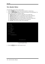
Page 190: ...des the information below Startup Times Record the boot strap times of the oscilloscope Software Version List the current software version of the oscilloscope FPGA Version List the current fpga versio...

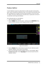
Page 191: ...re performing a self calibration Do the following steps to do self calibration 1 Disconnect all the input channels 2 Press the Utility button on the front panel and then press the Do Self Cal softkey...

Page 192: ...or when the prompt message pops up Press the Utility button on the front panel to enter the UTILITY function menu then press Sound softkey to select or to turn on or off the sound Language The oscillo...

Page 193: ...form must remain in order to comply with chosen parameters Compliance to the mask is verified point by point across the display The test results can be displayed on the screen as well as be declared t...

Page 194: ...ask P The frame number of the channel waveform that matches the mask T The frame number of the channel waveform that have been acquired It is the total of P and F 11 Press the Next Page softkey to go...

Page 195: ...function menu 7 Press the X Mask or Y Mask softkey and then turn the Universal Knob to select the desired value 8 Press the Location softkey to select Internal 9 Press the Save softkey to save the mas...

Page 196: ...the Location softkey to select External 9 Press the Save softkey to enter the file SAVE RECALL system 10 Save the test mask file refer to the Save to flie XXX msk chapter Recall Test Mask from Extern...

Page 197: ...waves and the arbitrary waveform generator which provides built in waveforms as well as the ability to create custom waveforms Built in waveforms are stored in the internal non volatile memory It inc...

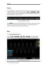
Page 198: ...etting System Remove Device Figure 93 AWG Menu Interface Press Output softkey to open or close the AWG output When the output is on the upper right corner of the oscilloscope interface will displays t...

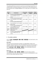
Page 199: ...gh Level Offset Low Level Width Width Fine value 1 uHz 10 MHz 4 mV 6 V 3 0 V Noise Stdev Mean value DC Offset value 3 0 V Arb Frequency Period Amplitude H igh Level Offset Low Level value 2 To set Ar...

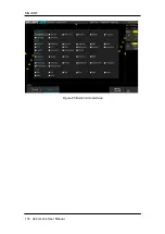
Page 200: ...SIGLENT 174 SDS2000X E User Manual Figure 95 Built in Arb interface...

Page 201: ...warning message will be displayed and the output will be disabled 4 Default Press Utility NextPage4 4 AWG Setting Default to recover the default values of the AWG Sine 1 000 kHz 4 000 Vpp 0 0 mVdc Hig...

Page 202: ...and then press the Save Upon completion of the zero adjust process the oscilloscope will display Zero Adjust Completed Systems 1 System Status Press Utility NextPage4 4 AWG System then select the Sys...

Page 203: ...pand the U disk directory select the firmware file ads then press the Press to update softkey an upgrade progress bar will be display on the interface Figure 98 AWG Update Interface 4 After the updati...

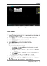
Page 204: ...e LAN Do the following steps to set the oscilloscope to communicate with a computer via LAN 1 Connect the oscilloscope to your local area network using the network cable 2 Press the Utility button on...

Page 205: ...ess the WiFi softkey to turn on or turn off the WIFI set menu Off The WIFI set menu off On You can set the SSID and PSK manually Manual Scan Press this softkey the oscilloscope will search the network...

Page 206: ...SIGLENT 180 SDS2000X E User Manual Figure 100 WiFi setting menu...

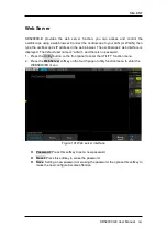
Page 207: ...isplayed The default user name is admin and there is no password 1 Press the Utility button on the front panel to enter the UTILITY function menu 2 Press the WebServer softkey on the fourth page of ut...

Page 208: ...otherwise the oscilloscope may be permanently damaged and may not restart again 8 After finish the update the screen will pop out the message Firmware decompressed Please restart and wait 9 Restart t...

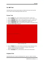
Page 209: ...UTILITY function menu 4 Press the Do Self Test softkey to enter the SELF TEST function menu 5 Press the Screen Test softkey to enter the screen test interface as the picture shown below the screen dis...

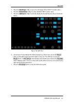
Page 210: ...03 Keyboard Test 6 To perform the knob and button test Knob test The default value is 0 Turn left to increase the value turn right to decrease Push the knob to set the value to 0 Test every knob rando...

Page 211: ...e shown below Figure 104 LED Test 6 According to the prompting information displaying on the screen press the Single button continually to light the button lights one by one The first time to press th...

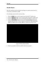
Page 212: ...2 Press the Next Page softkey to go to the second page of the UTILITY function menu 3 Press the Next Page softkey to go to the third page of the UTILITY function menu 4 Press the Screen Saver softkey...

Page 213: ...h the actual voltage level Press the Horizontal softkey to select Fixed Delay or Fixed Position Fixed Position When the time base is changed the oscilloscope will keep the horizontal offset indicator...

Page 214: ...ss the Next Page softkey to go to the third page of the UTILITY function menu 3 Press the Options softkey to enter the OPTION function menu Figure 106 OPTION Function Menu 4 Press the Type softkey the...

Page 215: ...SIGLENT SDS2000X E User Manual 189 Figure 108 Option Information...

Page 216: ...and output from a device under test DUT At each frequency the device gain and phase are measured and plotted on a Bode chart Perform Bode Plot This section gives an overview of the steps you must tak...

Page 217: ...ob to select the desired type USB Connect the oscilloscope USB Host to the external AWG s USB Device via a USB cable LAN Connect the oscilloscope and the external AWG to your local area network If LAN...

Page 218: ...ain values of each frequency point is the DUT output signal amplitude When Vout Vin mode is enabled the Y Axis can be set to linear or logarithmic by pressing Axis Type softkey When Vout mode is enabl...

Page 219: ...Scroll softkey then turn the Universal Knob to select the frequency point or press the Universal Knob then enter the number of the frequency point by the pop up keyboard 2 Press Save softkey Recall s...

Page 220: ...onfigured quickly This is especially true when a single instrument has multiple users Press Save Recall function key then press the Save softkey Select To Default Key and set the type to Factory Setup...

Page 221: ...connected to the item to be tested 4 Check whether there are signals generated from the item to be tested you can connect the probe compensation signal to the problematic channel to determine which ha...

Page 222: ...the IO Setting in Utility to make sure whether the setting in USB Device matches the device currently connected If needed restart the oscilloscope 8 The USB storage device cannot be recognized 1 Check...

Reviews: