SIG
L
ENT
SDS2000X-E User Manual
175
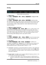
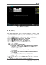
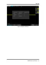
Setting
Figure 96 AWG Setting Interface
1. Output Load
Press
Utility
→
NextPage4/4
→
AWG
→
Setting
→
Output Load
to set
High-Z
or
50Ω
.
2. Sync Output
Press
Utility
→
NextPage4/4
→
AWG
→
Setting
→
Sync Output,
the AWG provides
Sync Output through the [Aux In/Out] connector on the rear panel. When the Sync Output
is on, the port can output a CMOS signal with the same frequency as basic waveforms
(except the Noise and DC), arbitrary waveforms, and modulated waveforms (except
external modulation).
3. OVP(over voltage protection)
Press
Utility
→
NextPage4/4
→
AWG
→
Setting
→
OVP
to turn on or off the function. If the
state is set to ON, overvoltage protection of the AWG output port takes effect once an
overvoltage condition is met. Overvoltage is defined as a condition in which the absolute
value of input voltage is higher than 4 V±0.5 V. When overvoltage protection occurs, a
warning message will be displayed and the output will be disabled.
4. Default
Press
Utility
→
NextPage4/4
→
AWG
→
Setting
→
Default
to recover the default values
of the AWG (Sine, 1.000 kHz, 4.000 Vpp, 0.0 mVdc, High-Z, Sync output off, OVP on).
5. Zero Adjust
Press
Utility
→
NextPage4/4
→
AWG
→
Setting
→
Zero Adjust
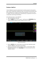
. The AWG can be
calibrated by using
Auto
mode or
Manual
mode. The calibration process configures the
AWG to output 0V DC. The signal is then measured on the 1 mV/div vertical scale. A
passing measurement has a mean value within a range of
±
1 mV.
Auto
mode:
This mode can only be performed with the channel 1 of the oscilloscope.
Connect the output of the AWG to the oscilloscope channel1, press the
Auto
softkey,
then the AWG starts to automatic calibrate. When completed, the scope will display ”
Zero Adjust Completed!”
Manual mode
:
The AWG can be manually calibrated through any channel on the
oscilloscope. Take channel 2 as an example:
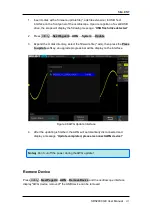
a) Connect the output of AWG to the oscilloscope channel 2, enable channel 2 on
the scope , set CH2 to DC coupling, open bandwidth limit, and probe attenuation
to 1X.
Summary of Contents for SDS2000X-E Series
Page 1: ...User Manual SDS2000X E Series Digital Oscilloscope UM0102E E01A SIGLENT TECHNOLOGIES CO LTD...
Page 14: ......
Page 69: ...SIGLENT SDS2000X E User Manual 43 Figure 13 x Interpolation Figure 14 Sin x x Interpolation...
Page 98: ...SIGLENT 72 SDS2000X E User Manual Figure 29 Relative Window Trigger...
Page 100: ...SIGLENT 74 SDS2000X E User Manual Figure 30 Interval Trigger...
Page 103: ...SIGLENT SDS2000X E User Manual 77 Figure 32 State Dropout Trigger...
Page 105: ...SIGLENT SDS2000X E User Manual 79 Figure 33 Runt Trigger...
Page 125: ...SIGLENT SDS2000X E User Manual 99 Figure 49 CAN Trigger...
Page 129: ...SIGLENT SDS2000X E User Manual 103 Figure 51 LIN Trigger...
Page 162: ...SIGLENT 136 SDS2000X E User Manual...
Page 200: ...SIGLENT 174 SDS2000X E User Manual Figure 95 Built in Arb interface...
Page 206: ...SIGLENT 180 SDS2000X E User Manual Figure 100 WiFi setting menu...
Page 215: ...SIGLENT SDS2000X E User Manual 189 Figure 108 Option Information...

