SIG
L
ENT
SDS2000X-E User Manual
5
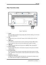
Connect the Power Supply
The power requirements of the oscilloscope are 100-240 Vrms, 50/60Hz or 100-120 Vrms,
440 Hz. Please use the power cord supplied with the instrument to connect the
oscilloscope to the power source.
Figure 4 Connect the Power Supply
Power-on Inspection
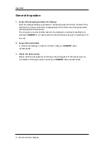
When the oscilloscope is energized, press the power key at the lower-left corner of the
front panel to start the oscilloscope. During the start-up process, the oscilloscope
performs a series of self-tests and you can hear the sound of relay switching. After the
self-test is finished, the welcome screen is displayed.
Connect the Probe
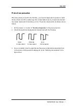
1. Connect the BNC terminal of the probe to a channel BNC connector of the
oscilloscope at the front panel.
2. Connect the probe tip to the circuit point to be tested and connect the ground alligator
clip of the probe to the circuit ground terminal.
Summary of Contents for SDS2000X-E Series
Page 1: ...User Manual SDS2000X E Series Digital Oscilloscope UM0102E E01A SIGLENT TECHNOLOGIES CO LTD...
Page 14: ......
Page 69: ...SIGLENT SDS2000X E User Manual 43 Figure 13 x Interpolation Figure 14 Sin x x Interpolation...
Page 98: ...SIGLENT 72 SDS2000X E User Manual Figure 29 Relative Window Trigger...
Page 100: ...SIGLENT 74 SDS2000X E User Manual Figure 30 Interval Trigger...
Page 103: ...SIGLENT SDS2000X E User Manual 77 Figure 32 State Dropout Trigger...
Page 105: ...SIGLENT SDS2000X E User Manual 79 Figure 33 Runt Trigger...
Page 125: ...SIGLENT SDS2000X E User Manual 99 Figure 49 CAN Trigger...
Page 129: ...SIGLENT SDS2000X E User Manual 103 Figure 51 LIN Trigger...
Page 162: ...SIGLENT 136 SDS2000X E User Manual...
Page 200: ...SIGLENT 174 SDS2000X E User Manual Figure 95 Built in Arb interface...
Page 206: ...SIGLENT 180 SDS2000X E User Manual Figure 100 WiFi setting menu...
Page 215: ...SIGLENT SDS2000X E User Manual 189 Figure 108 Option Information...


