34
SDS2000X HD Service Manual
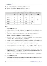
“ V
mean
” represents the measurement value on the oscilloscope.
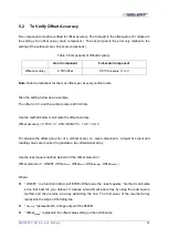
“ Offset
error
” represents the difference between V
mean
and V
setting
.
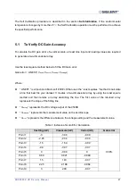
Table 6 Instance of Offset Gain Error Calculation
Vsetting
(V)
Offsetsetting
(V)
Vmean
(V)
Offseterror
(V)
Offset Gain
Error
Point 1
10
-10
10.1
0.1
-1%
Point 2
5
-5
5.05
0.05
Point 3
0
0
0
0
Point 4
-5
5
-5.05
-0.05
Point 5
-10
10
-10.1
-0.1
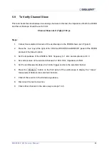
Steps:
1.
Set the 9500B output to On.
2.
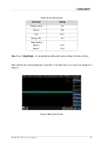
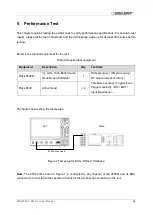
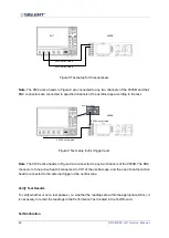
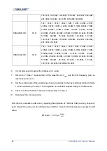
Connect a selected channel of the oscilloscope to the 9500B with an active head as shown in
3.
Set the timebase of the oscilloscope to
5 ms/div, the “ Max Mem Depth ” in the menu of
Acquire to 2M, and the impedance of the selected channel to 1
MΩ.
4.
Set the vertical scale of the channel to 2 V/div. Select the Measure menu of the oscilloscope
to display
the “ Mean ” measurement of the selected channel.
5.
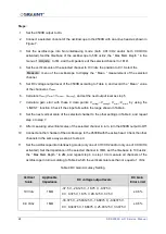
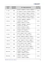
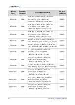
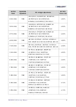
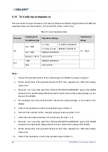
According to Table 7, set offset of the channel to Offset
setting
, and set the 9500B output level to
V
setting
= - Offset
setting
, then record the
“ Mean ” value of the oscilloscope as V
mean
.
6.
Calculate Offset
error
( Offset
error
= V
mean
- V
setting
), and set the next Offset
setting
as step 5.
7.
Calculate offset slope with these 5 data points: V
setting1
~V
setting5
, Offset
error1
~Offset
error5
by using
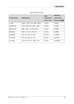
the ‘ LINEST ’ function. Check if the slope falls within the range of slope error shown in Table 7 .
8.
Set offset of the channel to 0 V, and turn the 9500B output to Off, then record the
“ Mean ” value
of the oscilloscope as V
zero
. Check if the V
zero
falls within the range of Full-Scale Component. Turn
the 9500B output to On for the next measurement.
9.
Set the vertical scale of the channel to the other settings in Table 7, and repeat step 5 to step 7.
10.
Turn the 9500B output to Off.
11.
Connect another channel of the oscilloscope to the 9500B with the active head. Check the other
channels in the same way as step 4 to step 10.

