62
SDS2000X HD Service Manual
8.4
To Check the Power Supply Module
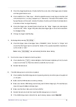
Disconnect all the external cables and devices from the front and back panel.
Disconnect the power cord from the oscilloscope, and wait until the power button light is off.
Remove the rear plastic cover and metal cover following the instructions in the chapter
Note that the power supply module is on the metal frame. It can be tested while attached to the
frame.
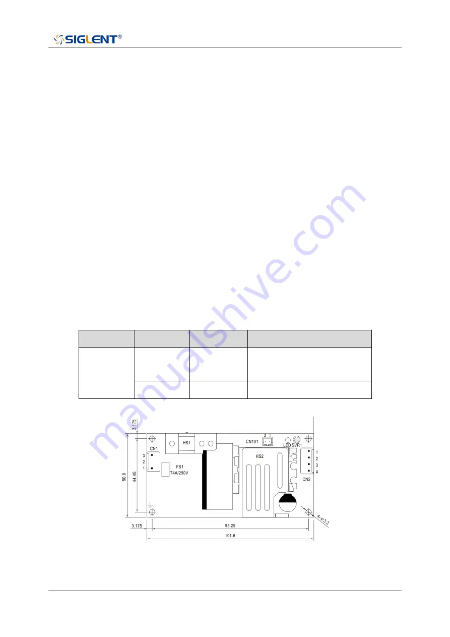
Disconnect the low-voltage side power supply cable from the power supply module labeled CN2.
Reconnect the power cord to the receptacle of the power supply module. Be cautious when
working near the power supply module without the protective cover, high voltage may exist on
the heat sink and other exposed conductors.
Test the power supply with a multi-meter.
If the voltage is slightly out of specification, try to adjust SVR1 on the power supply with a properly
insulated screwdriver.
Table 17 Pin assignments of connectors on board
Connector
Pin Number
Assignment
Specification
CN2
1, 2
V+
12.6 Vdc ± 0.2 Vdc (no load)
12.2 Vdc ~ 12.8Vdc (full load)
3, 4
COM
COM / GND
Figure 18 Power supply module mechanical drawing


