SDS5000X Series Digital Oscilloscope User Manual
WWW.SIGLENT.COM
161
Frame
— The oscilloscope triggers on the frame.
Set Frame header indicators: Payload preamble indicator, null frame
indicator, sync frame indicator, startup frame indicator.
Touch
ID
to set the frame ID by the universal knob or virtual keypad.
The range of ID is 0x000 to 0x7ff.
Touch
Compare Type
to select "=", ">" or "<". When set the
Compare
Type
as "=", the repetition factor is also required.
Touch
Cycle
to set the cycle count by the universal knob or virtual
keypad. The range of data value is 0 to 63.
Symbol
— The oscilloscope triggers on CAS/MTS (Conflict Avoidance
Symbol/ Media access Test Symbol) or WUS (Wake-up Symbol)
Errors
— The oscilloscope will trigger when a data error happens, including
errors on FSS, BSS, FES, Header CRC, and Frame CRC.
16.7.3 FlexRay Serial Decode
The configuration of FlexRay decoding is similar to that of I2C decoding.
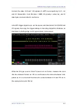
On the bus:
The signatures (CAS/MTS, WUP) are displayed in yellow green.
TSS transmission start sequence, displayed in yellow green. The null
frame indicator, the Sync frame indicator, and the Startup frame
indicator are displayed in the frame and displayed in pink.
The ID is displayed in the frame and is displayed in green.
PL (Valid Data Length) is displayed in frames, in words, in light
yellow.
Summary of Contents for SDS2000X Plus
Page 1: ...SDS5000X Series Digital Oscilloscope User Manual UM0105X E01E...
Page 2: ......
Page 158: ...SDS5000X Series Digital Oscilloscope User Manual 156 WWW SIGLENT COM Ack Acknowledge bit...
Page 165: ...SDS5000X Series Digital Oscilloscope User Manual WWW SIGLENT COM 163...
Page 240: ...SDS5000X Series Digital Oscilloscope User Manual 238 WWW SIGLENT COM...
Page 248: ...SDS5000X Series Digital Oscilloscope User Manual 246 WWW SIGLENT COM...
Page 361: ...SDS5000X Series Digital Oscilloscope User Manual WWW SIGLENT COM 359...

