SDS5000X Series Digital Oscilloscope User Manual
WWW.SIGLENT.COM
281
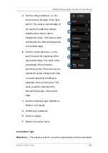
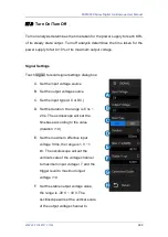
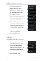
Touch
Signal
to recall signal settings dialog box:
A. Set the input voltage source
B. Set the input current source
C. Set the expected current value, the
range is 100 mA ~ 500 A. The
oscilloscope will set the trigger level
to expected current/20 and the
vertical scale of the current channel
to expected current/3.
D. Set the maximum effective input
voltage (Vrms), the range is 1 V ~ 1
kV. The oscilloscope will set the
vertical scale of the voltage channel
to maximum input voltage/6
E. View the connection guide
F. Return to previous menu
27.5
Switching Loss
Switch loss analysis can be used to calculate the power dissipated in the
switching period.
Deskew Calibration
A relatively small skew can cause a large measurement error of switching loss,
especially during the on phase when the voltage is close to zero and the non-
on phase when the current is close to zero. This is a typical oscilloscope
Summary of Contents for SDS2000X Plus
Page 1: ...SDS5000X Series Digital Oscilloscope User Manual UM0105X E01E...
Page 2: ......
Page 158: ...SDS5000X Series Digital Oscilloscope User Manual 156 WWW SIGLENT COM Ack Acknowledge bit...
Page 165: ...SDS5000X Series Digital Oscilloscope User Manual WWW SIGLENT COM 163...
Page 240: ...SDS5000X Series Digital Oscilloscope User Manual 238 WWW SIGLENT COM...
Page 248: ...SDS5000X Series Digital Oscilloscope User Manual 246 WWW SIGLENT COM...
Page 361: ...SDS5000X Series Digital Oscilloscope User Manual WWW SIGLENT COM 359...


