119 SNA5000A Vector Network Analyzer User Manual
domain and time-domain measurement parameters at the same time, first turn on the coupling
switch and select all the gating parameters in the coupling setting interface, at the same time,
the parameters of gate span are changed in time domain measurement, the frequency-domain
measurement parameters will be changed automatically to reflect the effect the time domain
gate span parameters are modified. The trace coupling is only applicable to Y-axis
scale/reference settings. The results of trace coupling do not change the measured data.
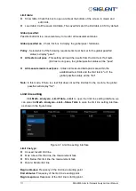
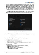
Click
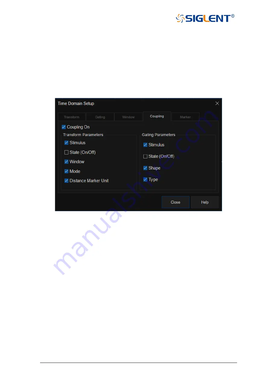
Math→Time Gating→Gating Setup→Coupling
to open the coupling setting
interface, we can set transmission parameters and gating parameters in this interface.
Figure 4-16 Coupling setting interface
Coupling on:
Click to enable coupling. At this time, all measurements in the channel are
coupled. The following conversion parameters and gating parameters can be
used for coupling.
Transform parameters:
⚫
Stimulus:
Setting of the start time, stop time, center time, and span.
⚫
State(On/Off):
State of the transform.
⚫
Window:
Kaiser Beta and pulse width parameter.
⚫
Mode:
Low pass pulse, low pass step, bandpass.
⚫
Distance marker unit:
When selected, all measured distance marker units are
coupled.
Gating parameters:
⚫
Stimulus:
Setting of the start time, stop time, center time, and span.
⚫
State(On/Off):
Switch of gating function.
⚫
Shape:
"Minimum", "normal", "wide" and "maximum".
⚫
Type:
Bandpass and notch filtering.
Summary of Contents for SNA5000A Series
Page 2: ......

