125 SNA5000A Vector Network Analyzer User Manual
5.5.4
Port Impedance
The port impedance can be set in the
Ref. Z
textbox in the
More Function
bar of the
Setup
tab, which defines the reference impedance to calculate the impedance values of the
traces under the format
Impedance
.
5.5.5
Velocity Factor & Dielectric Constant
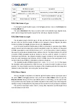
The velocity factor is the ratio of the velocity of the electric signal in the DUT to that in
the vacuum. VNAs calculate the distances by the transmission or reflection time based on
this factor, which provides the accurate positions of the impedance discontinuities. There is a
functional relationship between the velocity factor and the dielectric constant of the materials.
When either is changed, the other will be calculated by the equation below:
The velocity factor and dielectric constant can be set in the
Velocity Factor
and
Dielectric Const.
textboxes in the
More Function
bar of the
Setup
tab.
5.5.6
Power Level
The power level is the power of the test signal transmitted to the DUT, which can be set
in the
Source Power
spinbox in the
More Function
bar of the
Setup
tab.
5.5.7
Average
The average function means that the final measure results are equal to the average of
the measure results in the several sweeps in the same setting, and the number of sweeps
needed depends on the averaging factor. The average function can decrease the random
errors to some degree, but slow down the update of trace data. It's necessary to keep the
characteristics and connection of the DUT unchanged during an average sweep.
To enable or disable the average function, click the
Averaging
checkbox in the
Average
tar of the
Setup
tab. The average factor can be set in the textbox to the right of the
checkbox
.
5.5.8
IF Bandwidth
The IF bandwidth is the bandwidth of the intermediate-frequency filters in the receivers.
A narrow IF bandwidth leads to lower trace noise levels and longer sweep times.
The IF bandwidth can be set in the
IF Bandwidth
textbox in the
Average
tar of the
Setup
tab.
5.5.9
Trigger Mode
The trigger mode gates the channel sweep state change when the trigger signal is
detected. The trigger mode
Hold/Stop
means that sweep can't be started even if the trigger
signal is detected.
Single
means that only one sweep is triggered by the trigger signal. Upon
Summary of Contents for SNA5000A Series
Page 2: ......

