15 SNA5000A Vector Network Analyzer User Manual
1.3.4
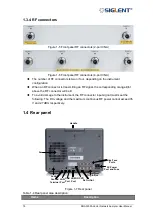
RF connectors
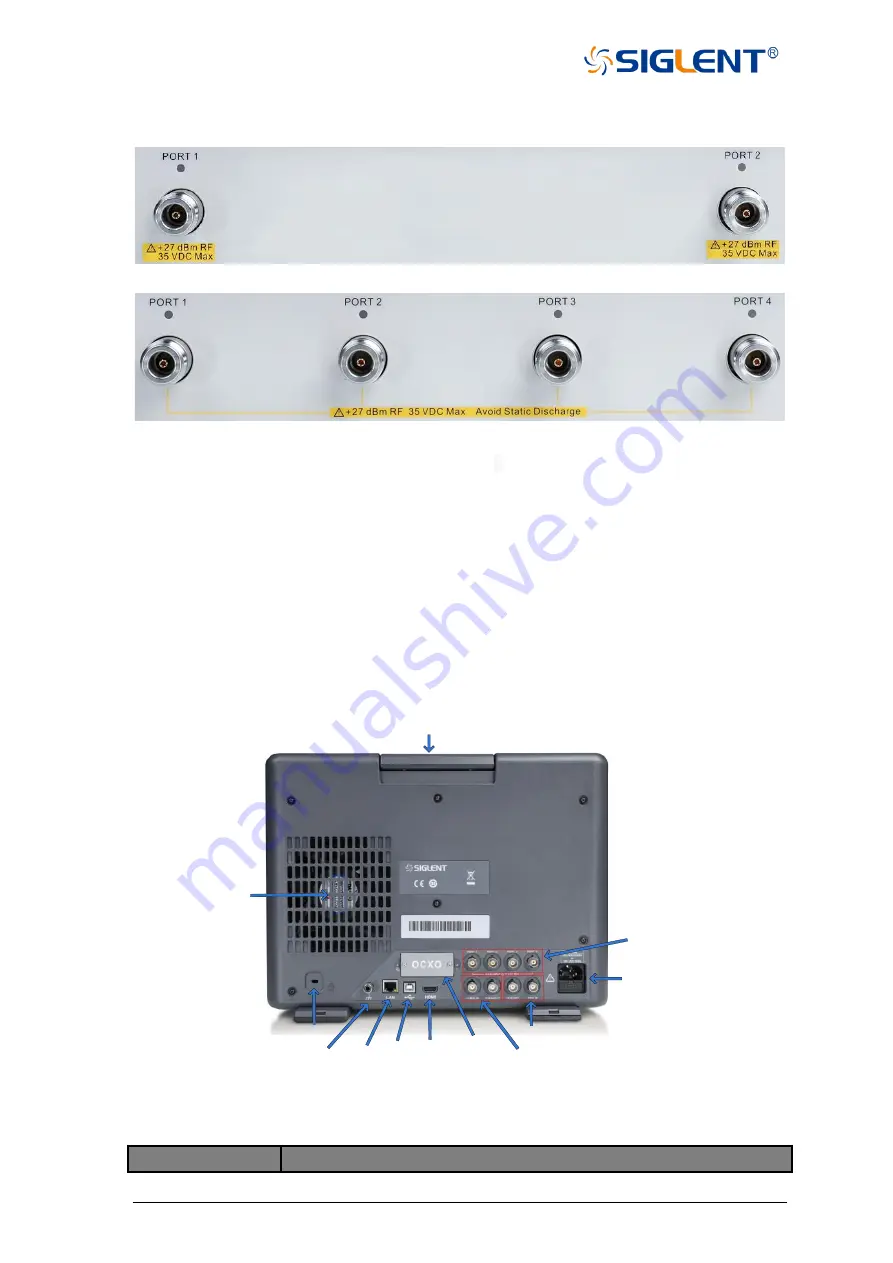
Figure 1-5 Front panel RF connectors (2-port VNA)
Figure 1-6 Front panel RF connectors (4-port VNA)
◆
The number of RF connectors is two or four
, depending on the instrument
configuration.
◆
When an RF connector is transmitting an RF signal, the corresponding orange light
above the RF connector will be lit.
◆
To avoid damage to the instrument, the RF connector input signal must meet the
following: The DC voltage and the maximum continuous RF power cannot exceed 35
V and 27 dBm respectively.
1.4 Rear panel
Ground
Terminal
LAN
Port
USB
Port
HDMI
Port
OCXO
Ref In/Out
Trig In/Out
Lock
AC Power
Port and Fuse
Bias-Tees
Ports
Fan
Handle
Figure 1-7 Rear panel
Table 1-4 Rear panel area description:
Items
Description
Summary of Contents for SNA5000A Series
Page 2: ......

