19 SNA5000A Vector Network Analyzer User Manual
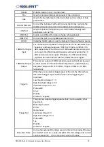
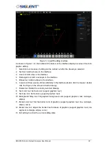
Add a marker.
Delete active window or trace.
Note: Keep at least one trace on the interface.
Screenshot (Ctrl+P)
1.6.2
Value of marker
Display the frequency and reading of the marker.
1.6.3
Trace State
◆
A trace is a series of measured data points. Up to 256 traces can be created. In addition,
one historical memory trace for each active trace can be stored and displayed.
Mathematical operations can be performed on the current trace data and the historical
memory trace.
◆
Press the
Display
button in the front panel, and the
Trace Setup
menu pops up on the
right side of the screen to manage the operation Trace, such as adding a trace, deleting a
trace, maximizing the trace window, moving traces between Windows, keeping the trace
to the maximum or minimum value without displaying the current value, etc.
◆
Select a trace line and press the
Scale
button to change the reference electric equalization
operation.
1.6.4
Channel State
◆
Channels contain traces. Up to 256 channels can be created. The channel setting
determines how trace data is measured, and all traces assigned to a channel share the
same channel setting.
◆
Press the
Display
button in the front panel, and the
Channel Setup
menu pops up on the
right side of the screen. This can be used to manage operation channels, such as adding
channels, copying channels, and deleting channels.
1.6.5
Function Keys
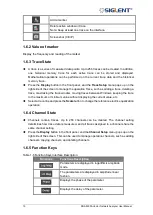
Table 1-6 Function Keys Interface Description
Functions
Functions Description
Parameters are displayed in logarithmic amplitude
mode.
The parameters are displayed in amplitude linear
fashion.
Displays the phase of the parameter.
Displays the delay of the parameter.
Summary of Contents for SNA5000A Series
Page 2: ......


