SNA5000A Vector Network Analyzer User Manual 20
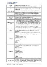
The parameters are shown in the form of a Smith
chart.
The parameters are displayed in polar coordinates.
The parameters are shown in SWR.
1.6.6
Label Page
Displays all parameter display formats supported by the vector network analyzer.
1.6.7
Window State
◆
Windows can be used to view trace data and up to 100 windows can be created.
◆
Press the button of
Display
in the front panel and the
Window Setup
menu pops up on
the right side of the screen. It can be used to manage operation windows, such as
selecting a window, adding a window, deleting a window, maximizing a window, layout,
and so on.
1.6.8
Stimulus Range
Displays the excitation signal set in the current window, including starting frequency, ending
frequency, internal source output power, etc.
1.6.9
Status Bar
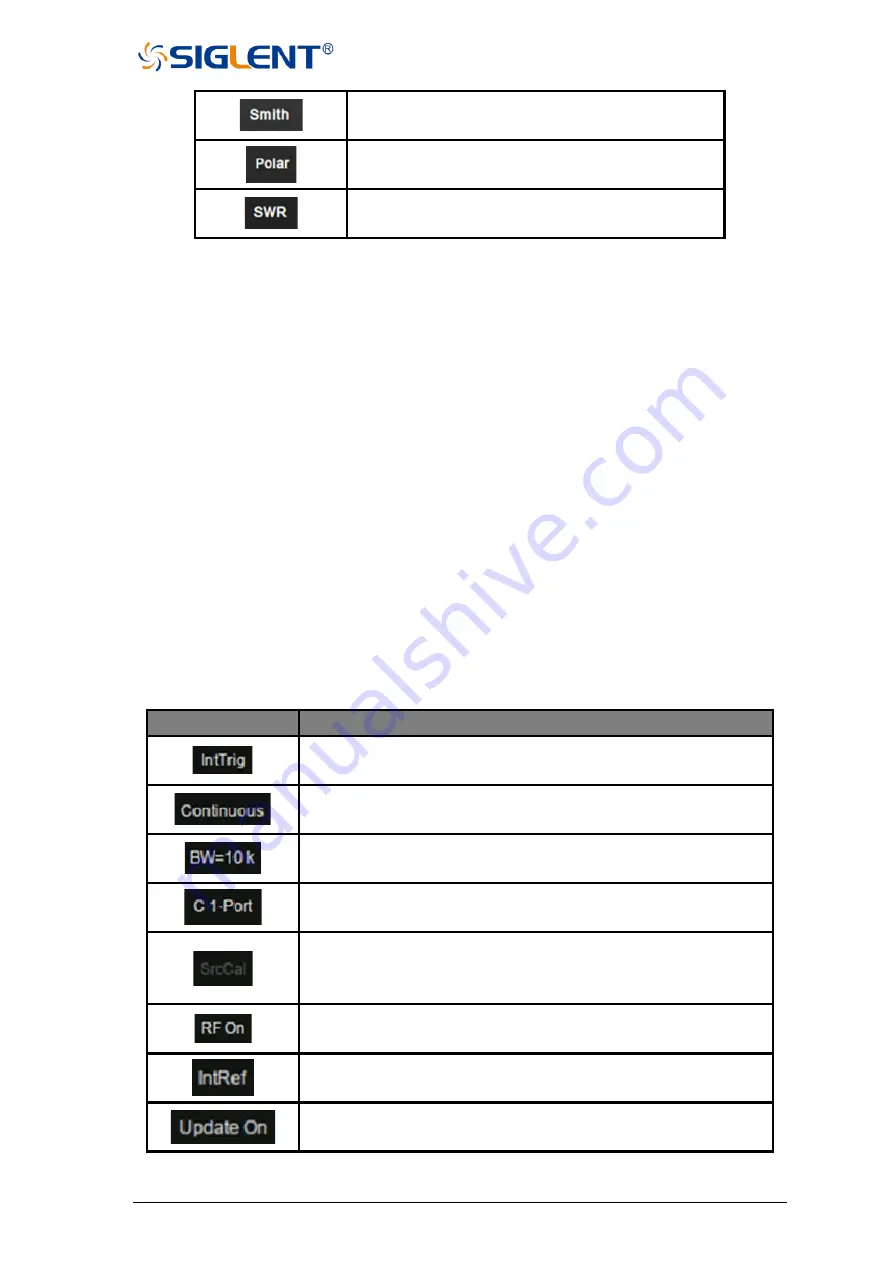
Table 1-7 Status Bar Interface Description
Functions
Functions Description
Displays the current trigger mode.
Continuous trigger, single trigger, and other trigger mode displays.
Display of the current IF bandwidth.
S parameter calibration data state loading display.
Display whether the internal source power calibration data state is
loaded or not. A Gray dark shaded label represents an unavailable
selection/option.
Internal source output power ON and off, RF ON stands for ON.
A display that currently uses an internal or external reference
signal.
UI waveform update or not.
Summary of Contents for SNA5000A Series
Page 2: ......


