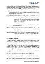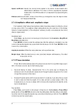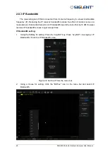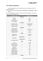
SNA5000A Vector Network Analyzer User Manual 52
Average
state
OFF
Smooth state
OFF
Calibration
Calibration state
unloaded calibration data
3
Measurement calibration
3.1 Overview
Usually, DUTs can't be measured directly and accurately due to cabling, adapters,
probes, and more. Calibration, compensation, and fixture simulation are introduced to help
achieve higher accuracy. These functions meet different measurement requirements, but
they all can be expressed as a matrix multiplication of the scattering parameter matrix and a
specific compensation matrix. The order of the matrix multiplication has a large influence on
the result. So it's important to understand the order of applying these functions and to design
a suitable physical connection to the DUT and expected measurement network.
Internal source power calibration and receiver calibration are applied before the
scattering parameter calculation, and the S parameter calibration is applied to the calculation
results. This provides the highest measurement accuracy at the calibration reference plane.
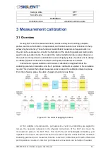
From the reference plane, the order of applying functions is as follow:
Figure 3-1 The order of applying functions
At first, adapter removal/insertion, port extension, 2-port de-embedding are applied to
remove the needless networks in the physical connections of the DUT and move the
measurement plane to the DUT. Then, Port match, N-port embedding/de-embedding, port
impedance conversion are used to embed or de-embed expected virtual networks. If balance
scattering parameters are measured, balance conversion, differential port match, differential
port impedance conversion, common port impedance conversion can be helpful if needed.
Summary of Contents for SNA5000A Series
Page 2: ......


