79 SNA5000A Vector Network Analyzer User Manual
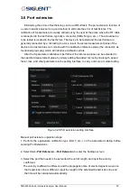
If the transmission line has loss, the loss of the transmission line can be added, including
DC and AC loss.
The AC loss can be selected as LOSS1 at the single-frequency point or LOSS1 and
LOSS2 at the dual-frequency point.
Among them, the fitting algorithm for two forms of AC loss are:
Single-frequency point loss Loss1:
Loss(f) = Loss1 * (f/Freq1) ^ 0.5
Dual-frequency point loss Loss1,Loss2:
Set the low frequency point to LOSS1 and the high frequency point to LOSS2,
Loss(f) = Loss1 * (f/Freq1) ^ n, n = lg [abs(Loss1/Loss2)] / lg (Freq1/Freq2).
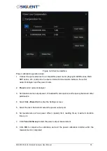
4. Select whether to coupling to the system speed factor. If unchecked, the speed factor is set
only for the specified port, and when checked, for all ports.
5. Check the
Port Extensions ON
button and the Port extension will take effect.
Manual port extensions require the user to manually enter the parameters of the extended
transmission line, while automatic port extension does not require prior knowledge of the
transmission line parameters. The calibration plane can be automatically extended to the
actual reference plane by simply performing an open or short circuit calibration on the actual
reference plane of the DUT. The automatic port extension function is not available in the
following cases:
1. The scan type is set to power scan.
2. The frequency offset is set to on.
3. Waveguide transmission line port extension.
Summary of Contents for SNA5000A Series
Page 2: ......


