SNA5000A Vector Network Analyzer User Manual 82
other words, all the uncovered low-frequency parameters are replaced by the first point in
the S2P file and all the uncovered high-frequency parameters are replaced by the last
point in S2P file making the frequency range of the S2P file the same as the frequency
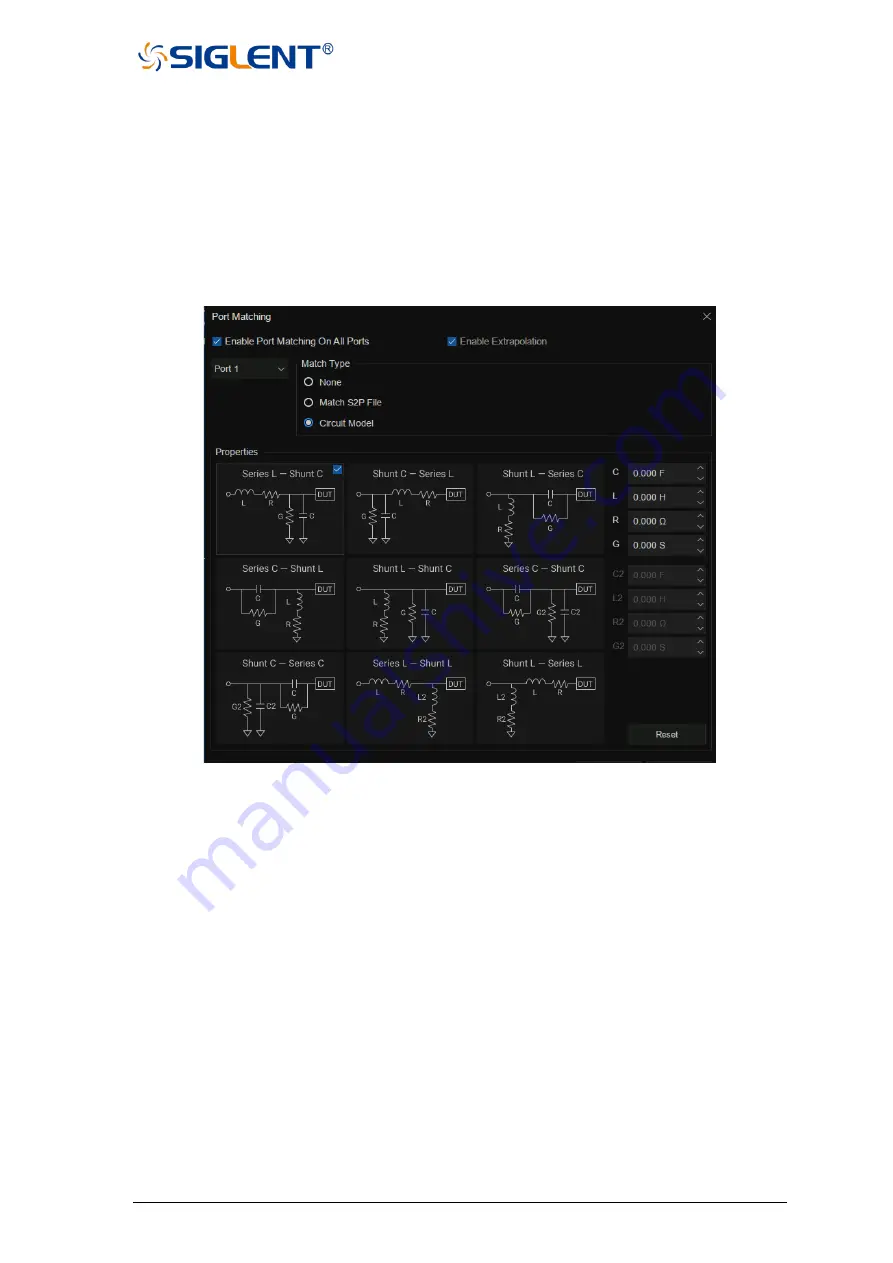
range of the current interface. If you check the
Enable Extrapolation
tab, the system will
interpolate the frequency points not covered by S2P so that the frequency range of the
S2P file is the same as that of the current interface.
4. Click
Close
to complete the setting and click
Apply Fixtures
to ON to take effect.
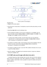
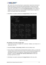
Figure 3-31 Port match
Port impedance conversion operation steps:
1. Ensure that the user has completed the S parameter calibration and obtained the S
parameters of the DUT.
2. Select
Cal
→
Fixtures
→
Fixture Setup
→
Port Z
to enter the Settings screen.
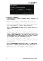
3. Choose the port, the default system port characteristic impedance is 50 Ω, you can fill in the
required resistance values in the R and JX columns, Then the S parameter displayed will be
automatically converted to the S parameter corresponding to the new characteristic
impedance. Checking the
Enable Port Z Conversion On All Ports
tab means port
matching is performed on all ports.
4. Click
Close
to complete the setting and click
Apply Fixtures
to ON to take effect.
Summary of Contents for SNA5000A Series
Page 2: ......


