SNA5000A Vector Network Analyzer User Manual 128
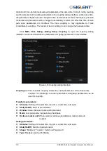
value in the
Stim. Ampl.
textbox in the
Basic
bar of the
Setup
tab. Intrinsically, the
Volt
format
means the trace data is a product of the T parameters and the magnitude of the stimulus signal.
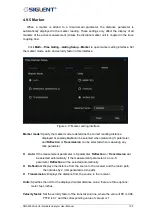
Click the measure parameter button in the grids on the left of the
Parameter
bar, the
measurement parameter of the current trace switches to the corresponding parameter. To
switch on or off the time domain transform of the current trace, click the pull-down menu in the
left of the
Measure
line. To switch to balance or unbalance parameters, click the pull-down
menu in the right of the
Measure
line. To change the format, click the
Format
pull-down menu.
5.6.5
Stimulus in Time Domain
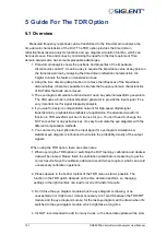
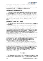
The stimulus type can be set in the
Stimulus
pull-down menu in the
Parameter
bar of
the
TDR/TDT
tab. There are two stimulus types to choose: The option
Lowpass Step
means
T parameters show the unit step responses and the option
Lowpass Impulse
means T
parameters show the unit impulse responses.
The rise time or impulse width of the stimulus signal can be set in the Rise Time or
Impulse Width textbox. Intrinsically, it controls the beta value of the Kaiser window function
applied in the time domain transformation to weaken the sidelobes. Because the
transformation is based on the finite frequency domain data, the data truncation at the end of
frequency domain data leads to some problems, such as the extension of the rise time or
impulse width of the responses signal and the appearance of sidelobes, which is called
"truncation effect". Applying the Kaiser window lowers the sidelobe levels, but aggravates the
extension of the rise time or impulse width and brings down the resolution ratio of
transformation. The longer the rise time or impulse width of the stimulus signal, the larger the
beta value of the Kaiser window function, the stronger effects explained above are introduced
into the transformation.
5.6.6
Smoothing
The smoothing function makes the trace data smooth by replacing the original trace data
with the average of the data nearby. If the local change ratios of trace data are relatively
large, the smoothing leads to large data errors. Therefore, the smoothing function is available
for the traces whose measure parameters are reflection S parameters.
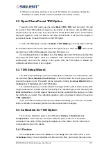
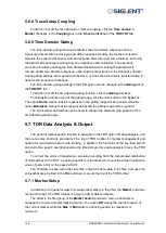
To switch on or off the smoothing function, click the
Smoothing
checkbox in the
Parameter
bar of the
TDR/TDT
tab.
5.6.7
Trace Allocation
The TDR option will delete all existing traces and windows, allocate all the traces and
windows automatically for the DUT topology, and set the traces to default settings if the trace
allocation function is activated. The operation deletes all original traces and their settings, but
the channel settings remain. There are three allocation methods to choose from: The option
Mixed
means that the traces in the time and frequency domain are allocated. The option
All
T
means that only traces in the time domain are allocated. The option
All S
means only
traces in the frequency domain. Note that in Single-ended 1 Port topology, only the option
Mixed
is available.
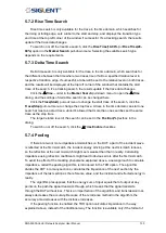
To use the trace allocation function, click the button of the corresponding method in the
Allocation
box in the
Trace Control
bar of the
TDR/TDT
tab.
Summary of Contents for SNA5000A Series
Page 2: ......

