SPA-900 Series User Manual 34
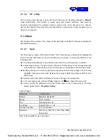
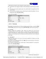
1. RF Input
Set the input impedance for voltage-to-power conversions. The default is 50Ω. To measure a 75Ω
device, you should use a 75Ω to 50Ω adapter to connect the analyzer with the system under test
and then set the input impedance to 75Ω.
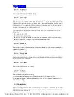
2. Apply Correction
Enable or disable amplitude correction and the default are Off. The spectrum analyzer provides
four correction factors and you can edit them separately.
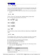
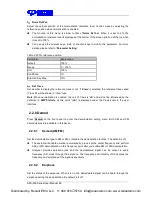
3. Edit Correction Factor
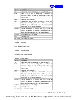
Table 2-10 Edit Correction table
Function
Explanation
Correction
Select the correction factor on or off.
Add Point
Add a point into correction table.
Point Num
Select a point to edit by point num.
Frequency
Edit the frequency value for the current selected point.
Amplitude
Edit the amplitude value for the current selected point.
Del Point
Delete the selected correction point.
Del All
Clear all data of the correction table.
Save/Load
Save or load correction data. Click this button to enter the file menu,
and the file type will be selected as COR. You can save the current
correction data into or load correction data from a specified file.
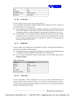
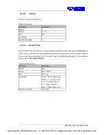
2.1.4 Auto Tune
Search for signals automatically throughout the full frequency range; adjust the frequency and
amplitude for optimum display effect of the signal to realize one-key signal search and auto setting
of parameters.
In the process of auto search, The “
Auto Tune
” is shown in the status bar on the screen until
the search is finished.
Some parameters such as the reference level, scale, input attenuation and maximum mixing
level may be changed during the auto search.
Distributed by: Reliant EMC LLC, +1 408 916
‐
5750, info@reliantemc.com, www.reliantemc.com

