SPA-900 Series User Manual 40
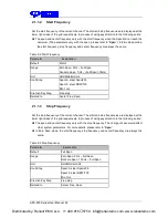
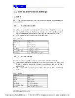
Table 2-15 Const
Parameter
Explanation
Default
0dB
Range
-300 dB ~ 300 dB
Unit
dB
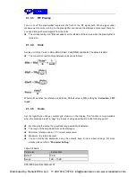
2.2.2.7
Output Z
The result Z will show on screen in trace A, B, C as you choose.
2.2.2.8
Calculation Type
Spectrum Analyzer provides the calculation types as shown below:
X-Y+Ref→Z
Y-X+Ref→Z
X+Y-Ref→Z
X+const→Z
X-const→Z
2.2.3 Detect
2.2.3.1
Detect Type
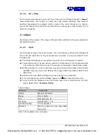
The analyzer displays the sweep signal on the screen in the form of trace. For each trace point, the
analyzer always captures all the data within a specific time interval and processes (Peak, Average,
etc.) the capture data using the detector currently selected, then display the processed data (one
point) on the screen.
Select an appropriate detector type according to the actual application in order to ensure the
accuracy of the measurement.
The available types are
Pos Peak
,
Neg Peak
,
Sample
,
Normal
,
Average
and
Quasi Peak
.
The default is
Pos peak
.
2.2.3.2
Positive Peak
For each trace point, Positive Peak detector displays the maximum value of data sampled within
the corresponding time interval.
2.2.3.3
Negative Peak
For each trace point, Negative Peak detector displays the minimum value of data sampled within
Distributed by: Reliant EMC LLC, +1 408 916
‐
5750, info@reliantemc.com, www.reliantemc.com

