background image


SPA-900 Series User Manual  72 

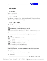
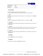
3.  Screen Text 

Open or close the current parameter and its value in the wave area. 
 

4.  Screenshot 

Select the screenshot type to normal and color inverse. 
The color of wave is not inversed in inverse mode. 

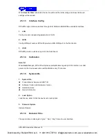
2.5.3 File 

2.5.3.1 

Browser 

Browser type including “

Dir

” and “

File

”,   

Dir: when selected, use the knob or direction keys to browser directory in system 
File:  when  selected,  use  the  knob  or  direction  keys  to  switch  among  files  or  folders  under  the 
current directory.   

2.5.3.2 

Open/Load 

Open the current folder or load current file


2.5.3.3 

View Type 

User  can define the file type be browsed, included

  “All  Type”,  “STA”, “TRC”, “COR”,  “CSV”, 

“LIM”, “PIC”

.


2.5.3.4 

Save Type 

User can define the file type be saved, included

 “STA”, “TRC”, “COR”, “CSV”, “LIM”, “JPG,” 

“BMP”, “PNG”

2.5.3.5 

Save 

Save file in current directory, the file type is set in "

Save Type

"   

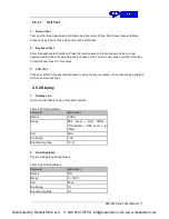
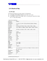
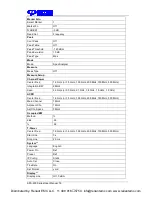
1.  STA(Status) 

STA  files  can  be  used  to  save  and  recall  the  instrument  configuration.


They  are  saved  in 

binary format, which is designed to be used by SSA3X instruments, not read by humans. 

2.  TRC(Trace) 

TRC files store the active (visible) trace data and scaling factors that were in place when the 
data was saved. They are saved  in binary format, which is designed to be used by  SSA3X 

Distributed by: Reliant EMC LLC,  +1 408 916

5750,  info@reliantemc.com, www.reliantemc.com

Summary of Contents for SPA-900 Series

Page 1: ...User Manual SPA 900 Series Spectrum Analyzer 2019 COM POWER CORPORATION Distributed by Reliant EMC LLC 1 408 916 5750 info reliantemc com www reliantemc com...

Page 2: ...Distributed by Reliant EMC LLC 1 408 916 5750 info reliantemc com www reliantemc com...

Page 3: ...the right to modify or change parts of or all the specifications or pricing policies at company s sole decision Any way of copying extracting or translating the contents of this manual is not allowed...

Page 4: ...uch as that caused by a thunderstorm can reach the product or else the operator might be exposed to danger of electrical shock Electrostatic Prevention Operate the instrument in an electrostatic disch...

Page 5: ...product DANGER Indicates direct injuries or hazards that may happen WARNING Indicates potential injuries or hazards that may happen CAUTION Indicates potential damages to the instrument or other prop...

Page 6: ...ed fields that meets a wider range of application requirements Features and Benefits All Digital IF Technology Frequency Range from 9 kHz up to 3 2 GHz 161 dBm Hz Displayed Average Noise Level Typ 98...

Page 7: ...Parameter Setting 21 1 8 Using Built in Help 22 1 9 Using the Security Lock 23 Chapter 2 Front Panel Operation 24 2 1 Basic Settings 25 2 1 1 Frequency 25 2 1 2 Span 29 2 1 3 Amplitude 30 2 1 4 Auto T...

Page 8: ...2 Couple 77 2 6 3 Help 77 2 6 4 Save 77 Chapter 3 General Inspection and Troubleshooting 78 3 1 General Inspection 78 3 2 Troubleshooting 79 Chapter 4 Service and Support 81 4 1 Maintain Summary 81 4...

Page 9: ...interface as well as announcements during first use of SPA 900 series spectrum analyzer Subjects in this chapter Appearance and Dimension Preparing for Use The Front Panel Rear Panel User Interface M...

Page 10: ...SPA 900 Series User Manual 8 1 1 Appearance and Dimension Figure 1 1 Front View Figure 1 2 Top View Distributed by Reliant EMC LLC 1 408 916 5750 info reliantemc com www reliantemc com...

Page 11: ...nd observation of the instrument Figure 1 3 Before adjusting Figure1 4 After adjusting 1 2 2 Connect to AC Power Supply The Spectrum Analyzer accepts 100 240V 50 60 440Hz AC power supply Please use th...

Page 12: ...escription NO Description NO Description 1 User Graphical Interface 2 Menu Control Keys 3 Function Keys 4 Knob 5 Arrow Keys 6 RF Input 7 Numeric Keyboard 8 TG Output 9 Earphone interface 10 USB Host 1...

Page 13: ...og power Power Voltage Filter Trace Selects Trace Trace setup Trace math Sweep Selects the Sweep time Sweep Rule Sweep Mode QPD Dwell Time Detect Selects the Detector type Trigger Used in Selecting th...

Page 14: ...the spectrum analyzer The states are as listed below 1 Power Switch Flash on and off alternatively in breathing state indicate the unit is in stand by state Constant on indicate the instrument is in n...

Page 15: ...h input 4 Back During the process of parameter editing press this key to delete the character on the left of the cursor 5 Esc During parameter editing process press this key to clear the inputs in the...

Page 16: ...store the current instrument state or trace in the USB storage device or store the contents currently displayed on the screen in the USB storage device in bmp or jpg format 3 Earphone Jack The analyze...

Page 17: ...through a cable with an N male connector CAUTION To avoid damage to the tracking generator the reverse DC voltage cannot exceed 50 V 5 RF INPUT CAUTION To avoid damage to the instrument for the signal...

Page 18: ...ugh this interface the analyzer can be connected to your local network for remote control 4 REF IN 10MHz SPA 900 can use internal or external reference source When a 10 MHz external clock signal is re...

Page 19: ...he 10MHz OUT and 10MHz IN connectors are usually used to build synchronization among multiple instruments 6 Trigger in In external trigger mode the connector receives an external trigger signal throug...

Page 20: ...5 EXT REF Ext Ref 6 Att Attenuator Value 7 Day and time System time 8 9 11 Cursor parameter 8 Current active cursor 9 current cursor frequency value 11 current cursor amplitude value 10 Auto Tune Auto...

Page 21: ...r or start frequency The frequency range of the current sweep channel can be expressed by the combination of center frequency or the combination of start frequency 24 25 26 27 Trace status Can set the...

Page 22: ...nu The unit of Y axis changes to dBm 4 Enter Lower Menu without parameter Press the corresponding menu key to enter the lower menu For example press Calibration to enter the lower menu directly 5 Dire...

Page 23: ...ob clockwise to increase or counterclockwise to decrease the parameter value at the specified step 1 Press Frequency Center Freq 2 Rotate the knob until the parameter is set to the desired value 100 M...

Page 24: ...p information will be shown at the center of the screen Then press the key that you want to get help of and the relevant help information will be shown at the center of the screen 2 Close the current...

Page 25: ...e Spectrum Analyzer to a fixed location The method is as follows align the lock with the lock hole and plug it into the lock hole vertically turn the key clockwise to lock the Spectrum Analyzer and th...

Page 26: ...cribes in detail the function keys at the front panel and the associated functions Subjects in this chapter Basic Settings Sweep and Function Settings Marker Set Measurement System Shortcut Key Distri...

Page 27: ...the current channel The center frequency and span values are displayed at the lower left and right sides of the grid respectively In process of using pay attention to the following points The start a...

Page 28: ...RBW 100 Min 1 Hz Direction Key Step Freq step Related to Center Freq Span 2 1 1 3 Stop Frequency Set the stop frequency of the current channel The start and stop frequencies are displayed at the lowe...

Page 29: ...1 10 of the span in Non zero span mode or equals the RBW while in Zero span mode in Manual mode you can set the step using the numeric keys Table 2 4 Frequency step Parameter Explanation Default Full...

Page 30: ...SPA 900 Series User Manual 28 Figure 2 1 Before Peak CF Figure 2 2 After Peak CF Distributed by Reliant EMC LLC 1 408 916 5750 info reliantemc com www reliantemc com...

Page 31: ...hen the center frequency is constant In manual span mode The span can be set down to 100Hz and up to the full span described in Specifications When the span is set to the maximum the analyzer enters f...

Page 32: ...ncy Period and 1 Time valid in Delta marker type 2 1 2 4 Zoom In Set the span to half of its current value At this point the signal on the screen is zoomed in to observe signal details 2 1 2 5 Zoom Ou...

Page 33: ...to Attenuator Preamp Ref Offset 2 1 3 2 Attenuator Set the front attenuator of the RF input in order to ensure big signals or small signals to pass through the mixer with low distortion or low noise R...

Page 34: ...notes the reference resistance Default value is 50 setting by Correction RF input 2 1 3 5 Scale Set the logarithmic units per vertical grid division on the display This function is only available when...

Page 35: ...ault unit Volts in Lin scale type when the scale type is charged from Log to Lin 2 1 3 7 Ref Offset Assign an offset to the reference level to compensate for gains or losses generated between the devi...

Page 36: ...tude Edit the amplitude value for the current selected point Del Point Delete the selected correction point Del All Clear all data of the correction table Save Load Save or load correction data Click...

Page 37: ...SPA 900 Series User Manual 35 Figure 2 3 Before Auto Tune Figure 2 4 After Auto Tune Distributed by Reliant EMC LLC 1 408 916 5750 info reliantemc com www reliantemc com...

Page 38: ...Hz Unit MHz kHz Hz Knob Step in 1 3 10 sequence Direction Key Step in 1 3 10 sequence Relation Span RBW VBW Sweep Time 2 2 1 2 Video Bandwidth Set the desired video bandwidth in order to filter out th...

Page 39: ...because it is the most common display and analysis scale for the video signal within a spectrum analyzer This scale is excellent for finding CW signals near noise 2 Power Average In this average type...

Page 40: ...f the current trace or disable it The system calculates the sampled data using a specific operation method according to the trace type selected and displays the result Trace types include Clear Write...

Page 41: ...race display and all measurements of this trace 2 2 2 3 Average Times Set the number of averages of the selected trace More averages can reduce the noise and the influence of other random signals thus...

Page 42: ...erval and processes Peak Average etc the capture data using the detector currently selected then display the processed data one point on the screen Select an appropriate detector type according to the...

Page 43: ...e testing ruled by CISPR For single frequency point the detector detects the peaks within QPD dwell time The peaks detected are weighted using circuit with specified charge and discharge structures as...

Page 44: ...the current sweep number 2 Numbers Set the number of sweeps for a single sweep In single sweep mode the system executes the specified number of sweeps and the number shown on the icon in the status ba...

Page 45: ...This FFT mode is only available when RBW is less than 30 kHz 2 2 4 5 QPD Dwell Time Dwell time is the measurement time at a single frequency QPD detector gets its weighted envelope response during dwe...

Page 46: ...0 dBm Range 300 dBm 50 dBm Unit dBm Knob Step 1 dB Direction Key Step 10 dB 3 External In this mode an external signal TTL signal is input from the TRIGGER IN connector at the rear panel and trigger...

Page 47: ...file 2 2 6 3 Limit2 Select eanble or disable limit2 2 2 6 4 Limit2 Edit Edit the properties of the limit2 lines Table 2 21 Limit2 Edit Menu Function Explanation Type Select the desired limit line uppe...

Page 48: ...he TG When the TG is enabled a signal with the same frequency of the current sweep signal will be output from the GEN OUTPUT 50 connector at the front panel The power of the signal could be set throug...

Page 49: ...he normalization When enabled the reference trace will be stored automatically after the current sweep finishes if no reference trace is stored before During the reference trace storage the correspond...

Page 50: ...is dB and will not be influenced by the definition in AMPT Units At this point dB is displayed under the Y axis scale in the user interface 2 2 8 Demod Press Demod at the front panel to enter the demo...

Page 51: ...r the demodulated signal through the earphone during the demodulation You can use the numeric keys knob or direction keys to modify this parameter For more details please refer to Parameter Setting Ta...

Page 52: ...r direction keys to modify the desired frequency or time as well as view the readouts of different points on the trace Figure 2 6 Marker 2 3 1 1 Select Marker Select one of the four markers and the de...

Page 53: ...ection keys to move the marker The readouts of the marker will be displayed at the upper right corner of the screen The readout resolution of the X axis frequency or time is related to the span For hi...

Page 54: ...ination of the marker number and letter R such as 1R and the Delta Marker marked by the marker number such as 1 You can use the numeric keys knob or direction keys to set the locations of the referenc...

Page 55: ...er number trace number marker readout type X axis readout and amplitude Through this table you can view the measurement values of multiple points The table allows for up to eight markers to be display...

Page 56: ...requency of the current marker If Delta or Delta Pair marker is selected the start frequency will be set to the frequency of the Delta Marker The function is invalid in Zero span mode 2 3 2 4 M Stop F...

Page 57: ...Noise marker function for the selected marker and read the noise power spectral density If the current marker is Off in the Marker menu pressing Noise Marker will first set it to Normal type automatic...

Page 58: ...lease refer to Parameter Setting Table 2 29 N dB Noise Parameter Explanation Default 3dB Range 100dB 100dB Unit dB Knob Step 0 1dB Direction Key Step 1dB 2 3 3 4 Freq Counter Turn on or off the freque...

Page 59: ...e is Frequency Note This type is invalid in Zero span mode 2 Period In this type Normal marker shows the reciprocal of frequency while Delta marker and Delta Pair marker show the reciprocal of frequen...

Page 60: ...t of minimum search is marked with the reference marker 2 3 4 6 Count Peak Enable or disable continuous peak search and the default is Off When enabled the system will always execute a peak search aut...

Page 61: ...minimum amplitude on both sides of it Peaks whose excursions are beyond the specified excursion are treated as real peaks Table 2 31 Peak Excursion Parameter Explanation Default 15dB Range 0dB 200dB...

Page 62: ...ues automatically Select ACPR and press Meas Setup to set the corresponding parameters 2 4 1 3 Occupied BW Integrate the power within the whole span and calculate the bandwidth occupied by this power...

Page 63: ...er and power spectral density Channel Power power within the integration bandwidth Power Spectral Density power in dBm Hz normalized to 1Hz within the integration bandwidth Measurement Parameters Cent...

Page 64: ...range of the sweep Modifying this parameter will change the span of the analyzer The channel power span is related to the integration bandwidth and the range available is from integration bandwidth t...

Page 65: ...ht channel and the main channel in dBc Measurement parameter center frequency main channel bandwidth adjacent channel bandwidth and channel spacing 1 Center Frequency Sets the center frequency this ce...

Page 66: ...rameter Explanation Default 2 MHz Range 100 Hz Sweep Span Unit GHz MHz kHz Hz Knob Step Integration BW 100 the minimum is 1 Hz Direction Key Step In 1 1 5 2 3 5 7 5 Sequence 4 Adjacent Channel space S...

Page 67: ...r within the whole span and then calculate the bandwidth occupied by the power according to the specified power ratio Transmit Frequency Error difference between the center frequency of the channel an...

Page 68: ...se the numeric keys knob or direction keys to modify this parameter Table 2 37 start line Parameter Explanation Default 1ms Range 0 s stop line Unit ks s ms us ns Knob Step Sweep time 751 Direction Ke...

Page 69: ...3 TOI TOI is automatic measurement do not need to set parameters 2 4 2 6 Spectrum Monitor Figure 2 14 Spectrum Monitor Display the power of spectrum in color spectrum Distributed by Reliant EMC LLC 1...

Page 70: ...A 900 Series User Manual 68 1 Spectrogram Sets the meas state of spectrum monitor 2 Restart Restart spectrum monitor Distributed by Reliant EMC LLC 1 408 916 5750 info reliantemc com www reliantemc co...

Page 71: ...led automatically at power on User If power on set to user the device will recall the specified configuration after power on 2 Preset Set the preset type to Default Last or one of User Def When press...

Page 72: ...t on the back board 2 5 1 4 Calibration Auto Cal When Auto Cal open SPA 900 will process self calibration regularly Within half an hour after power on the device executes a self calibration every 10 m...

Page 73: ...es 3 LCD Test If the keys at the front panel are transparent when the key is pressed the corresponding backlight will turn on when testing it 2 5 2 Display 1 Display Line Open or Close Display Line or...

Page 74: ...file 2 5 3 3 View Type User can define the file type be browsed included All Type STA TRC COR CSV LIM PIC 2 5 3 4 Save Type User can define the file type be saved included STA TRC COR CSV LIM JPG BMP...

Page 75: ...splay of the instrument screenshot as an image file All of the details of the display are captured exactly What you see on the display is in the file These are readable using image programs like Micro...

Page 76: ...00 MHz Start Freq 0 Hz Stop Freq 3 2 GHz or 3 0 GHz 2 1 GHz 1 8 GHz 1 5 GHz 1 0 GHz Freq Step Auto 320MHz or 300MHz 210MHz 180MHz 150MHz 100MHz Span Span 3 2 GHz or 3 0 GHz 2 1 GHz 1 8 GHz 1 5 GHz 1 0...

Page 77: ...able X A Variable Y B Constant 0 dB Output Z C Math Type Off Detect Select Trace A Detect Type of Trace A Pos Peak Limit Limit1 Off Limit Upper 0 dBm Limit2 Off Limit Lower 100 dBm Test Stop Fail to s...

Page 78: ...W 2 MHz Span 3 2 GHz or 3 0 GHz 2 1 GHz 1 8 GHz 1 5 GHz 1 0 GHz ACPR Center Freq 1 6 GHz or 1 5 GHz 1 05 GHz 900 MHz 750 MHz 500 MHz Main Channel 1 MHz Adjacent Chn 1 MHz Adj Chn Space 3 MHz Occupied...

Page 79: ...on Input attenuation have coupling relationship with Ref Level preamp Please refer to introduction of the amplitude 4 Freq step Freq step have coupling relationship with RBW at the zero span When in n...

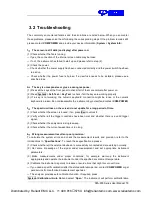
Page 80: ...rier will be responsible for damages to the instrument resulting from shipment COM POWER will not provide free maintenance or replacement 2 Inspect the instrument If the instrument is found to be dama...

Page 81: ...ctrum lines on the screen do not update for a long period of time 1 Check whether the screen is locked if so press Esc to unlock it 2 Verify whether all the trigger conditions have been met and whethe...

Page 82: ...ay prompt messages error messages or state messages according to the current working status These messages are displayed to help you to use the instrument correctly and are not instrument failures Dis...

Page 83: ...e repair or replacement as described in the complete warranty statement To arrange for service or obtain a copy of the complete warranty statement please contact your nearest COM POWER sales and servi...

Reviews: