background image

SIG

L

ENT


SSA3000X Plus User Manual 15


  Click on a screen parameter or menu for parameter selection or editing; 

  Open and drag the marker; 

  Use auxiliary shortcuts to perform common operations. 

You can turn the touch screen function on and off via 

Display

-

>’Touch Settings’. 


1.9  Remote Control 

The analyzer supports communication with computers via USB, LAN, and GPIB-USB interfaces. By 

using these interfaces, in combination with programming languages and/or NI-VISA software, users 

can remotely control the analyzer based on a SCPI (Standard Commands for Programmable 

Instruments) compliant command set, LabView and IVI (Interchangeable Virtual Instrument), to 

interoperate with other programmable instruments. 

You can also remote monitor and control the analyzer in Web Browser or Easy Spectrum. 

For more details, refer to the 

‘Programming Guide’ or contact your nearest SIGLENT office. 


1.10  Using Built-in Help 

The built-in help system provides information about every function key at the front panel and every 

menu soft key. 

  Press 

Help 

and the embedded help would show up. 

  Click on the items in the contents tree on the left to navigate to any topics interested. 

  Click the green back or forward arrow to go back or forward to the contents just read. 

  Click the close sign button in the top right corner or press the Esc front-panel key to quit the help 

system. 


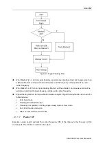
Figure 1-13 help information 

Summary of Contents for SSA3000X Plus

Page 1: ...SSA3000X Plus Spectrum Analyzer User Manual UM0703P E01A...

Page 2: ...publication replaces all previously corresponding material Any way of copying extracting or translating the contents of this manual is not allowed without the permission of SIGLENT SIGLENT will not b...

Page 3: ...ver All Terminals Ratings To avoid fire or electric shock please look over all ratings and sign instruction of the instrument Before connecting the instrument please read the manual carefully to gain...

Page 4: ...from an explosive atmosphere Any parts of the device and its accessories are not allowed to be changed or replaced other than authorized by the manufacturer or his agent Make sure not to position the...

Page 5: ...s on mains circuits Measurement Category Definitions Measurement category II is for measurements performed on circuits directly connected to the low voltage installation Examples are measurements on h...

Page 6: ...conforming to installation overvoltage category II WARNING Make sure that no overvoltage such as that caused by thunderbolt can reach the product or else the operator might expose to danger of electri...

Page 7: ...not store or leave the instrument in direct sunshine for long periods of time WARNING To avoid damages to the instrument or probe please do not leave them in fog liquid or solvent Cleaning Please per...

Page 8: ...de toutes les bornes des Pour viter le feu ou la d charge lectrique regardez svp au dessus de toutes les estimations et instruction de signe de l instrument Avant de relier l instrument lisez svp le...

Page 9: ...ne atmosph re explosive Afin d viter d endommager le dispositif ou les blessures il est important d utiliser le dispositif loin partir d une atmosph re explosive Maintenez les surfaces de produit prop...

Page 10: ...e propri t Limites sur le produit Ces limites peuvent appara tre sur le produit Le DANGER indique les dommages ou les risques directs qui peuvent se produire Dommages ou risques potentiels de WARNINGI...

Page 11: ...circuits directement reli s l installation de basse tension Les exemples sont des mesures sur des appareils lectrom nagers des outils portatifs et l quipement semblable La cat gorie III de mesure est...

Page 12: ...orie II d installation surtension EN AVERTISSANT assurez vous qu aucune surtension comme cela provoqu par coup de foudre ne peut atteindre le produit ou bien l op rateur pourrait exposer au danger de...

Page 13: ...g n ral et nettoyage Ne stockez pas ou ne laissez pas l instrument en soleil direct pendant de longues p riodes Pour viter d endommager l instrument svp ne les laissez pas dans le brouillard le liqui...

Page 14: ...ponenten Verschaffen Sie sich einen berblick ber alle Anschluss Ratings Um Br nde oder Stromschl ge zu vermeiden lesen Sie bitte alle Bemerkungen und Anweisungen des Ger tes Bevor Sie das Ger t anschl...

Page 15: ...e sofortige und direkte Verletzung oder Gef hrdung hin WARNUNG weist auf m glicherweise auftretende Verletzungen oder Gefahren hin VORSICHT weist auf m glicherweise auftretende Sch den am Ger t oder a...

Page 16: ...tshinweise und Symbole XV Chapter 1 Quick Start 2 1 1 General Inspection 3 1 2 Appearance and Dimension 3 1 3 Preparing for Use 4 1 3 1 Adjust the Supporting Legs 4 1 3 2 Connect to AC Power Supply 4...

Page 17: ...n Analyzer 64 3 1 Basic Settings 65 3 1 1 Frequency 65 3 2 Measurement 65 3 2 1 Digital Modulation Analysis 65 3 2 2 Analog Modulation Analysis 69 3 3 Sweep and Functions 70 3 3 1 Trigger 70 3 3 2 Swe...

Page 18: ...ting the Analyzer via the USB Device port 89 5 1 2 LAN Connecting the Analyzer via the LAN port 89 5 1 3 GPIB Connecting the Analyzer via the USB Host port 90 5 2 Build Communication 91 5 2 1 Build Co...

Page 19: ......

Page 20: ...mensions front rear panel and the user interface as well as announcements during the first use of the analyzer Subjects in this chapter General Inspection Appearance and Dimension Preparing for Use Fr...

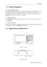
Page 21: ...onsible for damages to the instrument resulting from shipment SIGLENT will not provide free maintenance or replacement 2 Inspect the instrument If the instrument is found to be damaged defective or fa...

Page 22: ...servation of the instrument display Figure 1 3 before adjusting Figure 1 4 after adjusting 1 3 2 Connect to AC Power Supply The spectrum analyzer accepts 100 240V 50 60Hz or 100 120V 400Hz AC power su...

Page 23: ...scription NO Description NO Description 1 User Graphical Interface touch support 7 RF Input 2 Menu Control Keys 8 TG Output 3 Function Keys 9 3 5 mm Earphone interface 4 Knob 10 USB Host 5 Numeric Let...

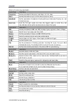
Page 24: ...tracking generator Including TG Level TG Level offset Normalization setup The backlight LED is on when TG source is working Demod Set the demodulation parameters of the AM and FM for audio listening M...

Page 25: ...cklight of TG turns on and turns off when the function is off 1 4 3 Using the Numeric Keyboard The analyzer provides a numeric keyboard at the front panel The numeric keyboard supports English upperca...

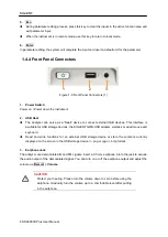
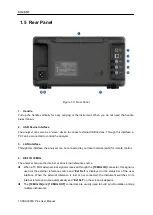
Page 26: ...ect external USB devices This interface is available for USB storage devices the SIGLENT GPIB USB adapter wireless or wired mouse and keyboard Read and write functions for an external USB storage devi...

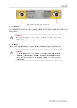
Page 27: ...To avoid damaging to the tracking generator the reverse DC voltage cannot exceed 50 V 5 RF INPUT The RF INPUT can be connected to the DUT through a cable with a male N type connector CAUTION To avoid...

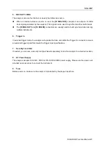
Page 28: ...can be connected to your local network LAN for remote control 4 REF IN 10 MHz The analyzer can use the internal or an external reference source When a 10 MHz external clock signal is received through...

Page 29: ...among multiple instruments 6 Trigger in In external trigger mode the analyzer will update the trace scan after the Trigger In connector receives an external trigger signal that meets the trigger input...

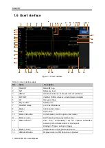
Page 30: ...Hz reference clock detected indicator 5 Att Attenuator Value 6 Day and time System time 7 Pass Fail status Limit Pass Fail status 8 Marker Current active marker 9 Trace Active trace 10 Marker instruct...

Page 31: ...onfigured 28 Touch assistant Click to open the commonly used functions for measurement such as peak search 29 30 31 32 Trace A B C D status Trace type C W Clear Write MaxH Max Hold MinH Min Hold View...

Page 32: ...xtract and copy the ADS file into the root directory of an USB stick 3 Plug the USB stick into the USB Host connector Press System System Info Firmware Update find the ADS file in USB stick 4 Press th...

Page 33: ...d set LabView and IVI Interchangeable Virtual Instrument to interoperate with other programmable instruments You can also remote monitor and control the analyzer in Web Browser or Easy Spectrum For mo...

Page 34: ...security lock please buy it yourself to lock the Spectrum Analyzer to a fixed location The method is as follows align the lock with the lock hole and plug it into the lock hole vertically turn the key...

Page 35: ...m Analyzer mode is the default mode of the machine In this mode the Mode backlight does not light up in other modes the Mode backlight will light up This chapter introduces in detail the function keys...

Page 36: ...requency will modify both the start frequency and stop frequency when the span is constant except when the start frequency or stop frequency reaches the boundary In Zero Span the start frequency stop...

Page 37: ...tails please refer to Span In Zero Span the start frequency stop frequency and center frequency are always the same value Table 2 3 Stop Frequency Parameter Explanation Default Full Span Range Zero Sp...

Page 38: ...tep modes Auto and Manual In Auto mode the Freq step is 1 10 of the span in Non zero span or equals the RBW while in Zero Span In Manual mode you can set the step using the numeric keys Table 2 5 Freq...

Page 39: ...and a peak search will be performed and then the peak frequency will be set to center frequency Signal tracking function is only available in sweep analysis Signal tracking function is turned off in f...

Page 40: ...F Step Set the current center frequency as the Freq Step At this point the Freq Step will switch to Manual mode automatically This function is usually used in channel switching For example in harmonic...

Page 41: ...nge in both Freq Step and RBW if they are in Auto mode Besides the change of RBW may influence VBW in Auto VBW mode Variation in the span RBW or VBW would cause a change in the sweep time Table 2 6 Sp...

Page 42: ...he screen will be reduced to gain more information about the nearby spectrum 2 1 2 6 Last Span Set the span to the previous span setting 2 1 2 7 X Scale Set the scale type of X axis to Linear Lin or L...

Page 43: ...scale mode step Scale 10 In Lin scale mode step 0 1 dBm Direction Key Step In Log scale mode step Scale In Lin scale mode step 1 dBm Related to Attenuator Preamp Ref Offset Note the maximum reference...

Page 44: ...n when the preamplifier is turned on 2 1 3 4 Units Set the unit of the Y axis to dBm dBmV dBuV dBuA Volts RMS or Watts Default is dBm The conversion relationships between units are as follows Where R...

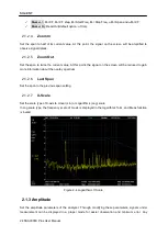
Page 45: ...when the scale type is changed from Lin to Log In Lin scale type the Y axis denotes the liner coordinate the values shown at the top of the grid and the bottom of the grid are the reference level and...

Page 46: ...edited separately but they can be applied independently in any combination 3 Edit Correction factors Table 2 11 Edit Correction table Function Explanation Correction Select the correction factor on o...

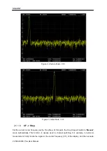
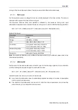
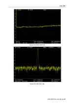
Page 47: ...SIGLENT SSA3000X Plus User Manual 29 Figure 2 5 before Auto Tune Figure 2 6 after Auto Tune...

Page 48: ...d by RBW RBW Filter shape factor LO Phase noise and LO Residual FM RBW varies with the span non zero span in Auto RBW mode Under EMI filter RBW can only be set to 200 Hz 9 kHz 120 kHz and 1 MHz with a...

Page 49: ...Step in 1 3 sequence Relation RBW VBW 2 2 1 4 Average Type Choose one of the following averaging types log power video power RMS or voltage averaging When trace average is on the average type is show...

Page 50: ...Trace The analyzer allows for up to four traces to be displayed at the same time Each trace has its own color Trace A Yellow Trace B Purple Trace C Light blue and Trace D Green All traces can be set p...

Page 51: ...lds the amplitude data of the selected trace The trace data is not updated as the analyzer sweeps 5 Blank Disable the trace display and all measurements of this trace 6 Average Set the averages times...

Page 52: ...interval and processes Peak Average etc the data using the detector currently selected then it displays the processed data a single data point on the screen Select an appropriate detector type accordi...

Page 53: ...odel that follows a defined response curve as well as the time constant specified in the CISPR 16 standards The measurement time for QP is far longer than Peak Detector 2 2 4 Sweep Sets parameters abo...

Page 54: ...le sweep mode the system executes the specified sweeps times and the number shown on the icon in the status bar at the left of the screen varies with the process of the sweep 3 Continue Set the sweep...

Page 55: ...gets its weighted envelope response during this dwell time The longer dwell time is the more sufficiently the QP detector responses to a single frequency and the more accurate the QP detector envelop...

Page 56: ...e measured curve will be compared with the pre edited curve If the related rules are met the result is Pass else the result is Fail 2 2 6 1 Limit1 Enable or disable limit1 2 2 6 2 Limit1 Edit Edit the...

Page 57: ...current point or line Del Point Delete the point whose number is selected in Mode Del All Delete all points Save Load Save or load the limit file 2 2 6 5 Test Enable or disable the limit test function...

Page 58: ...0 dBm 0 dBm Unit dBm Knob Step 1 dBm Direction Key Step 10 dBm 2 2 7 3 TG Level Offset Assigns a certain offset to the output power of the TG when gains or losses occur between the TG output and exter...

Page 59: ...en you change some parameters which will change the sweep frequency and sweep time the UNCAL sign will be displayed in the upper left corner of the screen indicating that the reference trace is no lon...

Page 60: ...Step 1 Direction Key Step 10 2 2 8 Demod Press Demod at the front panel to enter the demodulation setting menu Both AM and FM demodulations are available on the analyzer 2 2 8 1 Demod AM FM Set the de...

Page 61: ...y Step 1 2 2 8 4 Demod Time Set the time for the analyzer to complete a signal demodulation after each sweep If the Earphone is set to On you will hear the demodulated signal through the earphone duri...

Page 62: ...arker is active every time You can use the numeric keys knob or direction keys to modify the desired frequency or time as well as view the readouts of different points on the trace 2 3 1 1 Select Mark...

Page 63: ...orner of the screen The readout resolution of the X axis frequency or time is related to the span For higher readout resolution reduce the span 2 3 1 4 Delta One of the marker types It is used to meas...

Page 64: ...er will also be turned off 2 3 1 7 Relative To Relative to is used to measure the delta values of X Frequency or Time and Y Amplitude between two markers which can mark on different traces After the m...

Page 65: ...marker is selected the start frequency will be set to the frequency of the current marker If the Delta or Delta Pair marker is selected the start frequency will be set to the frequency of the Delta Ma...

Page 66: ...normalized noise power spectral density If the current marker is Off in the Marker menu pressing Noise Marker will first set it to Normal type automatically then measure the average noise level at th...

Page 67: ...rameter Explanation Default 3 dB Range 100 dB 100 dB Unit dB Knob Step 0 1 dB Direction Key Step 1 dB 2 3 3 4 Freq Counter Turn on or off the frequency counter The frequency readout is accuracy is up...

Page 68: ...r marker show the reciprocal of frequency difference When the frequency difference is zero the reciprocal is infinite and 100 Ts is displayed Note This type is invalid in Zero span 3 Time In this type...

Page 69: ...r measurement 2 3 4 7 Peak Table Open the peak table in the lower window which lists the peaks with frequency and amplitude that meet the peak search condition Up to 16 peaks can be displayed in the t...

Page 70: ...ser Manual Table 2 32 Peak Excursion Parameter Explanation Default 15 dB Range 0 dB 200 dB Unit dB Knob Step 1 dB Direction Key Step 5 dB 3 Peak Type Set the peak search condition The available option...

Page 71: ...s Setup to set the corresponding parameters 2 4 1 3 Occupied BW Integrates the power within the whole span and calculates the bandwidth occupied by this power according to the specified power ratio Th...

Page 72: ...amplitude of carrier signal must be greater than 50 dBm otherwise the measurement result is invalid Select Harmonics and press Meas Setup to set the corresponding parameters 2 4 1 9 Meas Off Turn off...

Page 73: ...ep Integration BW 100 the minimum is 1 Hz Direction Key Step In 1 1 5 2 3 5 7 5 sequence 3 Span Set the frequency range of the channel This span which is the same with the span of the analyzer is the...

Page 74: ...nd the main channel in dBc Measurement parameter Center frequency main channel bandwidth adjacent channel bandwidth and channel spacing 1 Center Freq Set the center frequency The center frequency is t...

Page 75: ...1 Hz Direction Key Step In 1 1 5 2 3 5 7 5 Sequence 4 Adj Chn space Set the difference between the center frequency of the main channel and the center frequency of the adjacent channels Adjusting thi...

Page 76: ...r T Power The power of the signal from the start line to the stop line Measurement Parameter Center frequency start line stop line 1 Center Frequency Set the center frequency this center frequency whi...

Page 77: ...his measurement is between the start line and stop line Table 2 39 stop line Parameter Explanation Default 900 us Range Start line sweep time Unit ks s ms us ns Knob Step Sweep time 751 Direction Key...

Page 78: ...um Monitor Display the power of spectrum of successive scans as a color map Also call a waterfall chart Measurement Parameter Spectrogram Restart 1 Spectrogram Sets the meas state of spectrum monitor...

Page 79: ...Knob Step Carrier BW 10 the minimum is 1 Hz Direction Key Step In 1 1 5 2 3 5 7 5 Sequence 2 Noise BW Set the bandwidth of the noise to be measured Table 2 41 Noise BW Parameter Explanation Default 3...

Page 80: ...he automatic mode is turned on the fundamental wave will be automatically found from the first scan If the automatic mode is turned off the user can input the fundamental frequency manually 2 Freq Ste...

Page 81: ...4 Select Harmonic When All is selected the trace shows the fundamental wave and all harmonics in the sweep bandwidth When 1 10 is selected the trace shows a zero span trace corresponding to the funda...

Page 82: ...follows AM analog modulation FM analog modulation ASK digital modulation FSK digital modulation 2FSK 4FSK 8FSK 16FSK MSK digital modulation PSK digital modulation BPSK QPSK 8PSK DBPSK DQPSK D8PSK Pi...

Page 83: ...n Unit GHz MHz kHz Hz Knob Step Freq Step 10 Direction Key Step Freq Step 3 1 1 2 Freq Step Setting the value of Freq Step will change the direction key step and knob step of the center frequency Tabl...

Page 84: ...s Symbol Set the points symbol of the modulated signal 3 2 1 4 Meas Length Set the number of symbols which will be used in calculating the measurement As the length is longer the range for statistics...

Page 85: ...e same as the transmitter Table 3 5 Filter Parameter Parameter Explanation Default 0 35 Range 0 1 Unit 1 Knob Step 0 01 Direction Key Step 0 1 4 Filter Length Set the symbols number of the filter sele...

Page 86: ...average function is turned on the average calculation of measurement results will be cleared and restarted as well 3 2 1 7 Trace The displayed data and format in the measurement windows can be set in...

Page 87: ...e to improve the S N ratio For AM modulation analysis the IFBW should be larger than twice the modulation frequency For FM modulation analysis the IFBW should be larger than twice the sum of the devia...

Page 88: ...rameter Parameter Default 10 Range 1 1000 Unit 1 Knob Step 1 Direction Key Step 10 3 2 2 4 Restart Meas After this function is performed the statistics will be cleared and restarted If the average fun...

Page 89: ...71 3 3 2 Sweep Select single or continue type for sweep Press Sweep into the menu When single sweep type is selected it will start a new sweep if meets the trigger even after press the menu button si...

Page 90: ...fied configuration after power on 4 1 2 2 Preset Set the preset type to Default Last or User Def When press Preset load the default settings for more details please refer to Table 4 3 Last When press...

Page 91: ...parameters are dynamically allocated The LAN status icon will be displayed in the upper right corner of the screen if the cable is connected Figure 4 1 LAN Config 4 1 3 2 GPIB Configure GPIB port num...

Page 92: ...nly mode VNC needs to be reopened 4 1 4 Calibration 4 1 4 1 Auto Cal Set whether to turn on the auto calibration or not and turn off by default When Auto Cal is turned on the analyzer will process sel...

Page 93: ...irmware Update and you will enter into the File menu Then you can select ADS file from memory to upgrade firmware After firmware upgrade the machine will restart Figure 4 4 Firmware Update 4 1 5 4 Sys...

Page 94: ...it the test press four times 3 LCD Test If the keys at the front panel are transparent when the key is pressed the corresponding backlight will turn on when testing it 4 Touch Test Test whether the to...

Page 95: ...5 Inverse color Screenshot 4 2 3 Touch Settings You can turn on or off touch screen settings and touch assistance Touch assistance can be moved to any position on the screen after the touch screen se...

Page 96: ...ont size label respectively Moreover you could change the size of the input area by dragging the two way arrows on the top and right Optional Add or delete annotation by clicking the plus sign button...

Page 97: ...rectory return to it 4 3 4 View Type Select the type of file to be browsed Include All Type STA TRC COR CSV LIM PIC JPG BMP PNG 4 3 5 Save Type Select the type of file to be saved The corresponding st...

Page 98: ...fined limit They are saved in ASCII format which can be read by humans 6 BMP Bitmap JPG JPEG PNG Picture files capture the display of the instrument screenshot as an image file All of the details of t...

Page 99: ...the preset setting and restore the analyzer to a specified status Press System Pwr On Preset Preset to select Def Last or User Press Preset to load the factory settings listed in the following table...

Page 100: ...ction x data Null BW RBW Auto 1MHz VBW Auto 1MHz VBW RBW 1 Avg Type Log Pwr Filter Gauss Sweep Sweep Time Auto Sweep Rule Speed Sweep Continue Sweep Mode Auto Numbers 1 QPD Dwell Time 50 ms Trig Trigg...

Page 101: ...t Lower 100 dBm Test Stop Fail to stop Off Buzzer Off X Axis Freq Demod Demod Mode Off Earphone Off Volume 6 Demod Time 5 00 s Marker Select Marker 1 Select Trace A Marker Type Normal Relative To 2 Ma...

Page 102: ...Chn 1 MHz Adj Chn Space 3 MHz Occupied BW Method dBc 26 99 T Power Center Freq 750 MHz Start Line 0 s Stop Line 60 6 us Spectrum Monitor Spectrogram Run CNR Carrier BW 3 MHz Noise BW 3 MHz Freq Offset...

Page 103: ...efault Measure Meas Type QAM Analog Modulation Frequency Center Freq 100 MHz Freq Step 10 kHz Span Span 13 08083 MHz Amplitude Attenuator Auto 20 dB Preamp Off BW EQBW 100 kHz Window Flat Top Sweep Sw...

Page 104: ...Trace A 1 5 Scale Div of Trace A 0 3 Ref Level of Trace B 0 dBm Scale Div of Trace B 10 dB Ref Level of Trace D 1 5 Scale Div of Trace D 0 3 BW EQBW 100 kHz Window Flat Top Sweep Sweep Continue Trig T...

Page 105: ...Avg Times 10 4 4 2 Couple Set related parameters according to the coupling relationship Auto all Set Related parameters automatically according to the coupling relationship 1 Freq step Freq step has...

Page 106: ...is set to on in one mode it applies to all other modes that support center freq setting so that you can switch between any of these modes while center freq will be unchanged When press All Off all of...

Page 107: ...you to set up a remote operation environment with a controller computer A controller computer could be a personal computer PC or a minicomputer Some intelligent instruments also function as controlle...

Page 108: ...way manually Press Apply Figure 5 3 LAN Config The analyzer will be detected automatically or manually as a new LAN point 5 1 3 GPIB Connecting the Analyzer via the USB Host port Refer to the followi...

Page 109: ...l named NI MAX that provides a user interface to control the device You can get NI VISA full version from http www ni com download After download you can follow the steps below to install it 1 Double...

Page 110: ...path is C Program Files National Instruments you can change it Click Next dialog shown as above 5 Click Next twice in the License Agreement dialog select the I accept the above 2 License Agreement s a...

Page 111: ...e LAN interface using the Transmission Control Protocol Internet Protocol TCP IP A socket is a fundamental technology used for computer networking and allows applications to communicate using standard...

Page 112: ...lorer It is an executable program that enables easy communication to troubleshoot issues with instrumentation 5 3 2 1 Using USB Run NI MAX software 1 Click Device and interface at the upper left corne...

Page 113: ...e at the upper left corner of the software 2 Find the Network Devices symbol click Add Network Devices 1 Select Manual Entry of LAN instrument select Next and enter the IP address as shown Click Finis...

Page 114: ...ows based remote control tool for Siglent s analyzer You can download it from Siglent s website To connect the analyzer via the USB LAN port to a PC you need install the NI VISA first It is able to be...

Page 115: ...be controlled through LAN from a web browser on PC and mobile terminals without any extra driver be installed This provides remote controlling and monitoring capabilities Screenshot and firmware upda...

Page 116: ...ling SIGLENT or returning an analyzer for service perform the quick checks listed below This check may eliminate the problem If the problem remains still please contact SIGLENT and provide your device...

Page 117: ...librate the instrument regularly to reduce or avoid errors that might occur over time If you need a specific calibration after the stated calibration period contact SIGLENT or get paid service from au...

Reviews: