SIG
L
ENT
26 SSA3000X Plus User Manual
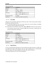
Table 2-8 Attenuator
Parameter
Explanation
Default
20 dB
Range
0 ~ 31 dB
Unit
dB
Knob Step
1 dB
Direction Key Step
5 dB
Related to
Preamp, Ref level
Note:
the maximum attenuator value of different machine models may be different, please refer to the
data manual specifically.
2.1.3.3
RF Preamp
Control the state of the internal preamplifier (PA) located in the RF input signal path. When the
signal-under-measurement is small, turning on the preamplifier can reduce the displayed noise level
and aid distinguishing small signals from the noise.
The corresponding icon “
PA
” will appear at the left side of the screen when the preamplifier is turned
on.
2.1.3.4
Units
Set the unit of the Y-axis to dBm, dBmV, dBuV, dBuA, Volts (RMS) or Watts. Default is dBm.
The conversion relationships between units are as follows.
Where, R denotes the reference impedance. The d
efault value is 50Ω and can be adjusted by pressing
“
Correction -> RF input
”. The “75 Ω” impedance is just a numeric value, not a real impedance. Setting
the RF input to 75 Ω will not change the actual input impedance. A 75 Ω feed-through adapter is
required to match 75 Ω circuits to the 50 Ω input of the analyzer.
2.1.3.5
Scale
Set the logarithmic units per vertical grid division on the display. This function is only available when the
scale type is set to “
log
”.
By changing the scale, the displayed amplitude range is adjusted.
The Minimum range: Reference level
–10 × current scale value.
The Maximum range: The reference level.

