SIG
L
ENT
34 SSA3000X Plus User Manual
2.
Input X, Y
Input X, Y can be applied to trace A, B, C, or D.
3.
Calculation Type
The analyzer provides the calculation types as shown below:
Power Diff:
X-
Y+Offset→Z
Power Sum:
X+Y+Offset→Z
Log Offset:
X+ Offset→Z
Log Diff:
X-Y-
Ref→Z
4.
Offset value
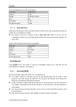
Table 2-16 Offset value
Parameter
Explanation
Default
0 dB
Range
-100 dB ~ 100 dB
Unit
dB
Knob Step
1 dB
Direction Key Step
1 dB
2.2.3 Detect
The analyzer displays the sweep signal on the screen in the form of a trace. For each trace point, the
analyzer always captures all the data within a specific time interval and processes (Peak, Average, etc.)
the data using the detector currently selected, then it displays the processed data (a single data point)
on the screen.
Select an appropriate detector type according to the actual application in order to ensure the accuracy
of the measurement.
The available types are
Pos Peak
,
Neg Peak
,
Sample
,
Normal
,
Average
and
Quasi Peak
. The
default is
Pos peak
.
1.
Positive Peak
For each trace point, Positive Peak detector displays the maximum value of data sampled within the
corresponding time interval.
2.
Negative Peak
For each trace point, Negative Peak detector displays the minimum value of data sampled within the
corresponding time interval.
3.
Sample
For each trace point, Sample detector displays the transient level corresponding to the central time

