SDG5000 User Manual 80
voltage of the [Sync] connector is level low.
In the Inverse Mode, the Waveform that corresponds to the Sync Signal
does not inverse.
The Sync Signal is a Pulse Signal with fixed positive pulse width, which is
more than 50ns.
For non-modulated waveform, the Sync Signal reference is the carrier.
For internal modulating AM, FM and PM, the Sync signal reference is the
modulated signal (not the carrier signal).
For ASK and FSK, the Sync Signal Reference is the keying Frequency.
For a Sweep, when the sweep starts, the Sync Signal becomes TTL
Level High. The Sync frequency equals the specific Sweep time.
For the Burst, when the burst starts, the Sync Signal is Level High.
For the External Gated Burst, the Sync Signal follows the External Gated
Signal.
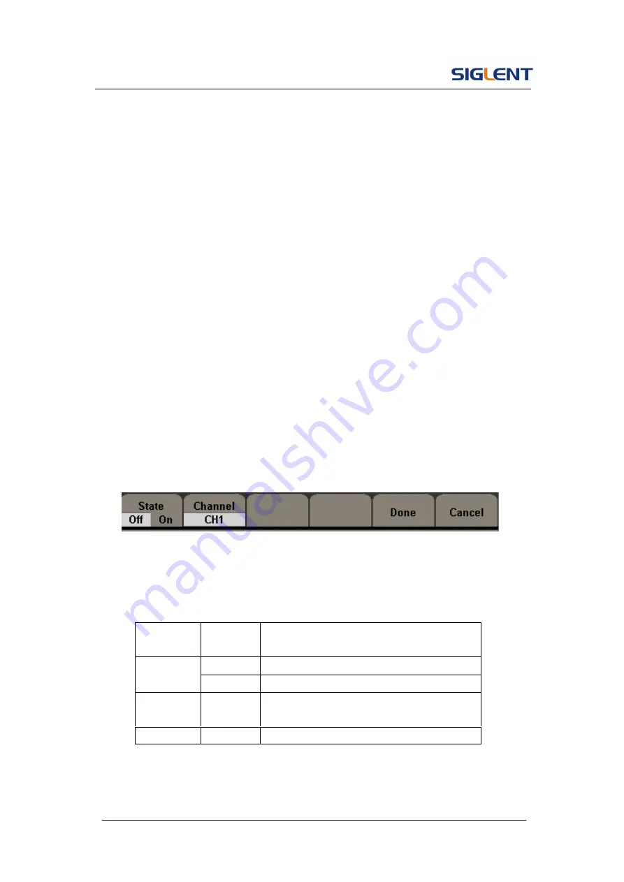
Figure 2- 57
Table 2- 29 Menu Explanations of Output Setting (Page 1/2)
Function
Menu
Settings
Explanation
Off
Close the sync output
State
on
Open the sync output
Channel
CH1
CH2
Set the sync signal of channel 1
Set the sync signal of channel 2
Done
Finish operation.
Summary of Contents for SDG5000 series
Page 38: ...SDG5000 User Manual 27 Figure 2 5 Setting the Offset ...
Page 109: ...SDG5000 User Manual 98 Figure 3 1 Sine Waveform ...
Page 111: ...SDG5000 User Manual 100 Figure 3 2 Square Waveform ...
Page 129: ...SDG5000 User Manual 118 3 12 Figure 3 12 FSK Waveform ...
Page 135: ...SDG5000 User Manual 124 Figure 3 15 DSB AM Waveform ...


