background image


SDG6000X Service Manual


  68 


WWW.SIGLENT.COM   
mM 


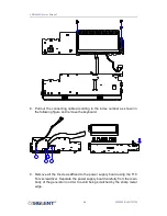
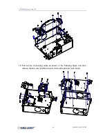
8.  Pull  out  the connecting cable  according to the  index  number  as shown  in 

the following figure and remove the keyboard. 

1

3

2

4


9.  Remove all the 9 screws  affixed to the power supply board using the T10 

Torx screwdriver. Separate the power supply board carefully from the main 
body of the generator in order to avoid being scratched by the sharp metal 
edge. 

Summary of Contents for SDG6000X Series: SDG6022X

Page 1: ...SDG6000X Series Pulse Arbitrary Waveform Generator Service Manual SM0206X E01A 06X E01A...

Page 2: ......

Page 3: ...n this publication replaces all previously corresponding material Any form of copying extracting or translating the contents of this manual is not allowed without the permission of SIGLENT SIGLENT wil...

Page 4: ...rrectly before connect its input or output terminals Connect the Signal Wire correctly The potential of the signal wire is equal to the earth do not connect the signal wire to a high voltage Do not to...

Page 5: ...an injury or hazard that may immediately happen WARNING Indicates an injury or hazard that may not immediately happen CAUTION Indicates a potential damage to the instrument or other property that migh...

Page 6: ...rm 38 To Generate a Noise Waveform 41 To Set the DC Voltage 43 To Output a Built In Arbitrary Waveform 45 To Use the Built In Help System 47 Chapter 3 Calibration 48 Calibration Interval 48 Adjustment...

Page 7: ...g 74 Check the Power Supply 75 Check the Channel Board 77 Voltage Checking 77 10 MHz Clock Source Checking 78 FPGA Checking 78 Connector Checking 78 Check the Main Board 79 Voltage Checking 79 ARM CPU...

Page 8: ...er 2 describes how to prepare the generator for use and helps to familiarize you with a few of its front panel features Calibration Chapter 3 provides calibration verification and adjustment procedure...

Page 9: ...Models Addressed by this Manual All the description for function and performance in this document are according to the SDG6052X series generator and apply to all generators in this series The SDG6000...

Page 10: ...00 MHz maximum bandwidth 20 Vpp maximum output amplitude high fidelity output with 80 dB dynamic range High performance sampling system with 2 4 GSa s maximum sampling rate and 16 bit vertical resolut...

Page 11: ...ing function High precision Frequency Counter 196 kinds of built in arbitrary waveforms Standard interfaces USB Host USB Device USBTMC LAN VXI 11 Socket Telnet Optional interface GPIB 4 3 touch screen...

Page 12: ...SDG6000X Service Manual 10 WWW SIGLENT COM mM The Front Panel at a Glance USB Host Numeric Keyboard Knob Power Switch User Interface Menu keys Function Keys Channel Control Arrow Keys...

Page 13: ...ger or a touch pen to control the instrument Most functions and selections can be chosen using the touch screen in a similar manner to the front panel keys and knob 1 Waveform Display Area Displays th...

Page 14: ...and assumes a load impedance of 1 M Load Displays the set impedance value The default is 50 and the range is from 50 to 100 k Note This setting does not actually change the instrument s output impeda...

Page 15: ...This mark indicates the current clock source is from an external clock source 8 Menu Shows the menu corresponding to the selected function Click menu options on the screen to select and set the corres...

Page 16: ...ce The Rear Panel at a Glance WARNING For protection from electric shock the grounding power cord must not be defeated If only a two contact electrical outlet is available connect the instrument s cha...

Page 17: ...ing 1 1 ppm 25 10 year aging 3 5 3 5 ppm 25 Sine Characteristics Parameter Min Typ Max Unit Condition Note Frequency 1 500M Hz SDG6052x 1 350M Hz SDG6032x 1 200M Hz SDG6022x Harmonic distortion 65 dBc...

Page 18: ...nge 2 n s 10 90 Overshoot jitter output range and pulse width accuracy specifications are only guaranteed in specified rise fall times range Fall time specified range 2 n s Rise fall times resolution...

Page 19: ...etry 0 100 Linearity 1 Percentage of peak output 1 kHz 1 Vpp 50 symmetry Output Range Note 2 m 20 Vpp Note The specification will be divided by 2 while applied to a 50 load Noise Parameter Min Typ Max...

Page 20: ...load Accuracy 1 2 mV HiZ load IQ optional Parameter Min Typ Max Unit Condition Note Symbol rate 250 37 5M Symb s Limited by the oversampling factor Vertical resolution 16 bit Modulation type 2ASK 4ASK...

Page 21: ...pp 10 kHz sine 0 V offset Amplitude flatness 0 3 0 3 dB 50 load 0 5 Vpp compare to 1 MHz Sine Output impedance 49 5 50 50 5 100 kHz sine Output current 200 200 mA Crosstalk 60 dBc CH1 CH2 0 dBm Sine 5...

Page 22: ...source is Internal PM Parameter Min Typ Max Unit Condition Note Carrier Sine Square Ramp Arb Modulation source Internal External Modulation wave Sine Square Ramp Noise Arb Phase deviation 0 360 Modula...

Page 23: ...Modulation wave Sine Square Ramp Noise Arb Modulation frequency 1 m 1 M Hz While modulation source is Internal Pulse width deviation resolution 3 3 ns Burst Parameter Min Typ Max Unit Condition Note C...

Page 24: ...0 MHz 200mVrms 2 5 V DC coupling 100 MHz 200 MHz 500mVrms 2 5 V DC coupling Above 200 MHz 100mVrms 5 Vpp AC coupling 100 MHz 200mVrms 5 Vpp AC coupling 100 MHz 200MHz 500mVrms 5 Vpp AC coupling Above...

Page 25: ...ion Note VOH 3 8 V IOH 8 mA VOL 0 44 V IOL 8 mA Output impedance 100 Pulse width 26 7 ns Jitter 3 3 ns Peak to peak Frequency 10 MHz Modulation Input Parameter Min Typ Max Unit Condition Note Frequenc...

Page 26: ...e temperature 20 60 Operating humidity 5 90 30 5 50 40 Non operating humidity 5 95 Operating altitude 3048 m 30 Non operating altitude 15000 m Calibration Parameter Min Typ Max Unit Condition Note Cal...

Page 27: ...amiliar with some of its front panel operations This chapter is divided into the following sections To Prepare the Generator for Use To Adjust the Carrying Handle To Set the Output Frequency To Set th...

Page 28: ...on self test which takes several seconds The generator powers up in the sine wave function at 1 kHz with an amplitude of 4 V peak to peak CH1 At power on the Output connector is disabled To enable the...

Page 29: ...00X Service Manual 27 WWW SIGLENT COM mM To Adjust the Carrying Handle To adjust the handle position of SDG6000X please grip the handle by the sides and pull it outward Then rotate to the desired posi...

Page 30: ...eady to modify using the numeric keypad 2 Press the Frequency Period softkey The displayed frequency is either the power on value or the frequency previously selected When changing the waveform type t...

Page 31: ...SDG6000X Service Manual 29 WWW SIGLENT COM mM Note The desired numerical value can be modified using the knob and direction keys...

Page 32: ...or the amplitude previously selected When changing the waveform type the same amplitude is used if the current value is valid for the new waveform To set the HighLevel for the waveform press the soft...

Page 33: ...SDG6000X Service Manual 31 WWW SIGLENT COM mM...

Page 34: ...r the offset previously selected When changing the function the same offset is used if the current value is valid for the new waveform To set the LowLevel for the waveform press the softkey again to s...

Page 35: ...SDG6000X Service Manual 33 WWW SIGLENT COM mM Note The desired numerical value can be modified using the knob and direction keys...

Page 36: ...w to change the duty cycle to 80 1 Select the square wave function Press Waveforms Square to select the square function and then select the desired output frequency to 1 kHz 2 Press the DutyCycle soft...

Page 37: ...SDG6000X Service Manual 35 WWW SIGLENT COM mM...

Page 38: ...symmetry to 60 1 Select the Ramp wave function Press Waveforms Ramp to select the pulse function and then select the desired output frequency to 1 MHz 2 Press the Symmetry softkey The displayed symme...

Page 39: ...SDG6000X Service Manual 37 WWW SIGLENT COM mM...

Page 40: ...ime of 8 ns and delay time of 50 ns 1 Select the pulse function Press Waveforms Pulse to select the pulse function and output a pulse waveform with the default parameters 2 Set the Pulse period Press...

Page 41: ...X Service Manual 39 WWW SIGLENT COM mM 4 Set the Edge Time Press the Rise Fall softkey and then set the rising edge to 10ns 5 Set the Pulse Delay Press the Delay softkey and then set the delay time to...

Page 42: ...SDG6000X Service Manual 40 WWW SIGLENT COM mM...

Page 43: ...h an adjustable Stdev and Mean The following steps show you how to generate a noise waveform with 500mV Stdev and 1mV Mean 1 Select the Noise function Press Waveforms Noise to select the noise functio...

Page 44: ...SDG6000X Service Manual 42 WWW SIGLENT COM mM 3 Set the Mean Press the Mean softkey and then set the mean to 1 mV...

Page 45: ...w how to set a dc voltage with 1 Vdc 1 Select the DC function Press Waveforms Page 1 2 DC to select the DC function 2 Set the DC Offset Use the digital keypad to input the value directly enter the val...

Page 46: ...SDG6000X Service Manual 44 WWW SIGLENT COM mM...

Page 47: ...ed in non volatile memory The following steps show how to output the built in exponential fall waveform from the front panel 1 Set the arbitrary waveform function Press Waveforms Page 1 2 Arb Type Bui...

Page 48: ...vice Manual 46 WWW SIGLENT COM mM 3 Output the exponential fall waveform Rotate the knob to select the ExpFall waveform and press the knob The waveform is output with the present settings unless they...

Page 49: ...some functions A list of help topics is also available to assist you with several operations 1 Read the help information Press Utility System Page 1 2 Help to enter the following interface You will s...

Page 50: ...l you select SIGLENT recommends that re adjustment should always be performed within the calibration interval This is necessary to ensure the accuracy of the performance data measured during the calib...

Page 51: ...mperature is stable and between 18 and 28 Ideally the calibration should be performed at 23 1 Assure ambient relative humidity is less than 80 Allow a 30 minute warm up period before verification or a...

Page 52: ...ribed in the table below and measure the output voltage with the DMM Be sure the generator output load is set to High Z and the output is enabled DC Offset CH1 CH2 Spec Range 1 2 mV 0 mV 2 mV 2 mV 10...

Page 53: ...Sine waveform of the generator and set the amplitude to the values listed below in sequence Amplitude Vpp CH1 Vpp CH2 Vpp Spec Range 1 1 mVpp 11 10 889 11 111 5 6 5 543 5 657 2 1 979 2 021 0 9 0 89 0...

Page 54: ...Sine waveform of the generator and set the amplitude to 0 5 Vpp and frequency to the values listed below in sequence Frequency CH1 dBm CH2 dBm Spec Range dBm 1 MHz 2 3412 1 7412 5 MHz 2 3412 1 7412 10...

Page 55: ...SDG6000X Service Manual 53 WWW SIGLENT COM mM 5 Compare the value measured from Power Meter to the spec range shown in the table above...

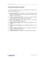
Page 56: ...hannel Adjustment which acts as a standard calibration module providing the accuracy assurance for Self Adjust Channel Self Adjustment which includes internal control channel adjustment and signal cha...

Page 57: ...xls it is necessary that you are working with MS Office 2003 or higher version 3 NI VISA The Python module PyVisa is based on VISA I O library which can be derived from NI VISA Warming up Before perf...

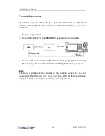
Page 58: ...urn on the generator 2 Connect the DMM PC and SDG6000X generator as shown below 3 Double click and run the script ChannelAdjust py prepared previously Then Change the channel connection according to t...

Page 59: ...channels when perform self adjustment This adjustment must be performed prior to Self Adjust to make sure it is performed based on the best adjusting accuracy 1 Connect the DMM PC and SDG6000X genera...

Page 60: ...nal channels 1 After the feedback channel adjustment is completed disconnect the two BNC cables on CH1 and CH2 2 Input the password 123654 under the system info interface to show the SelfCal menu and...

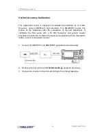
Page 61: ...calibration after the completion of the self adjustment It calibrates the Sine wave with a 10 kHz frequency and selects several amplitudes to calibrate Compare the measured amplitude with the standard...

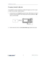
Page 62: ...ibrate the trigger level of the counter to obtain more accurate measured values 1 Connect the PC and SDG6000X generator with a USB cable and connect the CH1 at the front panel to the counter port at t...

Page 63: ...the PC using a USB cable 2 Connecting the USB end of the Power Meter to the USB port of the PC upon which the Power Meter indicator light will be brightened Only after the indicator light goes out fro...

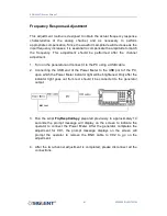
Page 64: ...gh accuracy 10 MHz signal with a BNC cable as shown below 2 Press Utility button on the front panel and select System Page 1 2 System Info Use the number keyboard to input 123654 Then select the TimeB...

Page 65: ...edures Whenever possible disconnect the power supply before removing or replacing modules Otherwise personal injuries or damages to the components may occur Avoid Electric Shock Hazardous voltages exi...

Page 66: ...immediate work area Use only anti static solder suckers List of Modules The following removable modules are listed in the order of performing disassembly procedures Number of Module Module 1 Handle 2...

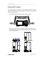
Page 67: ...s listed above in detail Complete disassembly will be best achieved through the following operating steps 1 Pull out the handle firmly from the two sides of the generator 2 After removing 4PCS screws...

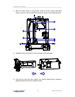
Page 68: ...pull out the cable as shows and then remove the 5PCS screws as shown in the following figure 1 2 6 5 3 4 4 Separate the front panel from the main body of the generator 5 Pull out the knob and then rem...

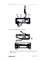
Page 69: ...SDG6000X Service Manual 67 WWW SIGLENT COM mM 6 Remove the keypad circuit board assembly 7 Remove the 3PCS screws holding the screen bracket and remove the metal front panel...

Page 70: ...number as shown in the following figure and remove the keyboard 1 3 2 4 9 Remove all the 9 screws affixed to the power supply board using the T10 Torx screwdriver Separate the power supply board care...

Page 71: ...SDG6000X Service Manual 69 WWW SIGLENT COM mM 10 Pull out the connecting cable as shown in the following figure and then remove the fan rear interface board channel board and main board...

Page 72: ...SDG6000X Service Manual 70 WWW SIGLENT COM mM Note To assemble the generator please follow these same steps in reverse order...

Page 73: ...g any internal test of the generator please refer to the following precautions to avoid damages to its internal modules or components resulting from ESD Handle circuit boards by their edges as much as...

Page 74: ...signal conditioning board for generating analog signal It mainly deals with the adjusting of signal parameters such as frequency amplitude and so on Please refer to the following drawing to quickly l...

Page 75: ...SDG6000X Service Manual 73 WWW SIGLENT COM mM...

Page 76: ...the generator that contains an ARM CPU system It completes the GUI function controlling and configuration function of the channel board as well as the user interface Please refer to the following dra...

Page 77: ...the other four pins that are marked respectively with blue yellow red and white using a digital multimeter to check whether the voltage value is within the corresponding specified range The voltage pa...

Page 78: ...that is out of the specified range then the power supply module appears to be problematic and a replacement will be required For safety please use qualified technical personnel to disassemble the pow...

Page 79: ...ied range using a digital multimeter The voltage parameters to be tested are listed in table 5 4 Voltage Checking Test the voltage points on the channel board in the table below To locate the test poi...

Page 80: ...blinks at a 2 Hz rate in normal operation If it does not light cannot be lighted or blinks at an incorrect frequency then the FPGA may be fault Connector Checking Table 5 5 Connectors of the Channel...

Page 81: ...d range then the main board is working normally If the voltages are out of the specified range please return it to the factory for repair or contact SIGLENT Table 5 6 Test Voltages of the Main Board T...

Page 82: ...ork normally please contact SIGLENT 2 Starts up with a dark screen 1 Check the connection between the power supply and the channel board 2 Check the connection between the keypad circuit board and the...

Page 83: ...SIGLENT makes no warranty of any kind express or implied including without limitation the implied warranties of merchantability and fitness for a particular purpose In no case shall SIGLENT be liable...

Page 84: ...ed in 2005 SIGLENT has become the fastest growing manufacturer of digital oscilloscopes We firmly believe that today SIGLENT is the best value in electronic test measurement Headquarter SIGLENT TECHNO...

Reviews: