SIGLENT
18 SSG5000X Service Manual
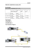
Figure 3-1 Absolute amplitude accuracy connections
Test Procedures
1. Connect the output terminal of the SSG5000X with the power meter, as
shown in Figure 3-1 (a).
2. Set the SSG5000X to output a sine waveform with -10 dBm amplitude. Then
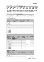
modify the output frequency of the SSG5000X according to Table 3-2 and
enable the RF output switch
RF
.
3. Modify the frequency of the power meter accordingly each time the output
frequency of the SSG5000X is modified. Read the amplitude measurement
value
A1
and record it to the test record form.
4. Disconnect the SSG5000X and the power meter. Connect the
[10 MHz OUT]
terminal of the signal analyzer with the
[EXT REF IN]
terminal at the rear panel
of the signal generator using dual-BNC cable to synchronize the two
instruments.
5. Connect the output terminal of the SSG5000X with the input terminal of the
signal analyzer using dual-N cable as shown in Figure 3-1 (b).
6. Configure the signal analyzer:
1) Select the external frequency reference input.
2) Set the span to 100 Hz.
3) Set the reference level to -20 dBm.
4) Set the input attenuation to 10 dB.
5) Set the resolution bandwidth to 1 Hz.
6) Set the self-calibration to normal and perform all of the calibration
items.
7. Set the output frequency of the SSG5000X and the center frequency of the
signal analyzer according to Table 3-2 (the center frequency of the signal
analyzer corresponds to output frequency of the SSG5000X).
8. Each time the center frequency is changed, wait for the instrument to finish a
sweep and press
Peak Search
to find the maximum peak. Then record the
result
A2
to the test record form.
9.
System Error
(the input attenuation of the signal analyzer is 10 dB)
= A2 -
A1
and record the measurement result.
10. Keep the connection shown in Figure 3-1 (b) unchanged, press
Mode
Preset
to restore the signal analyzer to its factory setting and set the output
amplitude of the SSG5000X according to Table 3-3.
11. Each time the output amplitude is changed, set the output frequency of the
SSG5000X and the center frequency of the signal analyzer according to Table
3-2 (the center frequency of the signal analyzer corresponds to output
frequency of the SSG5000X).
12. Each time the center frequency is changed, wait for the instrument to finish
a sweep; then, press
Peak Search
to find the maximum peak and record the
measurement result
A3
to the test record form.
Note:
when the output amplitude of the SSG5000X is -10 dBm, the
measurement result
A3
, namely, is the measurement value
A2
of the signal
analyzer in step 8.
13. Calculate the
Global Error = A3 - Reference Value
and record the result.
14. Calculate the amplitude accuracy using the formula
Amplitude Accuracy
= |Global Error - System Error|
and compare the calculation result with the
specification.


