10
Logging may also be started and stopped by connecting a dry contact between DI1 and digital
common. It is necessary to remove the screen panel to access this terminal block. Logging
occurs whenever these points are closed.
Press
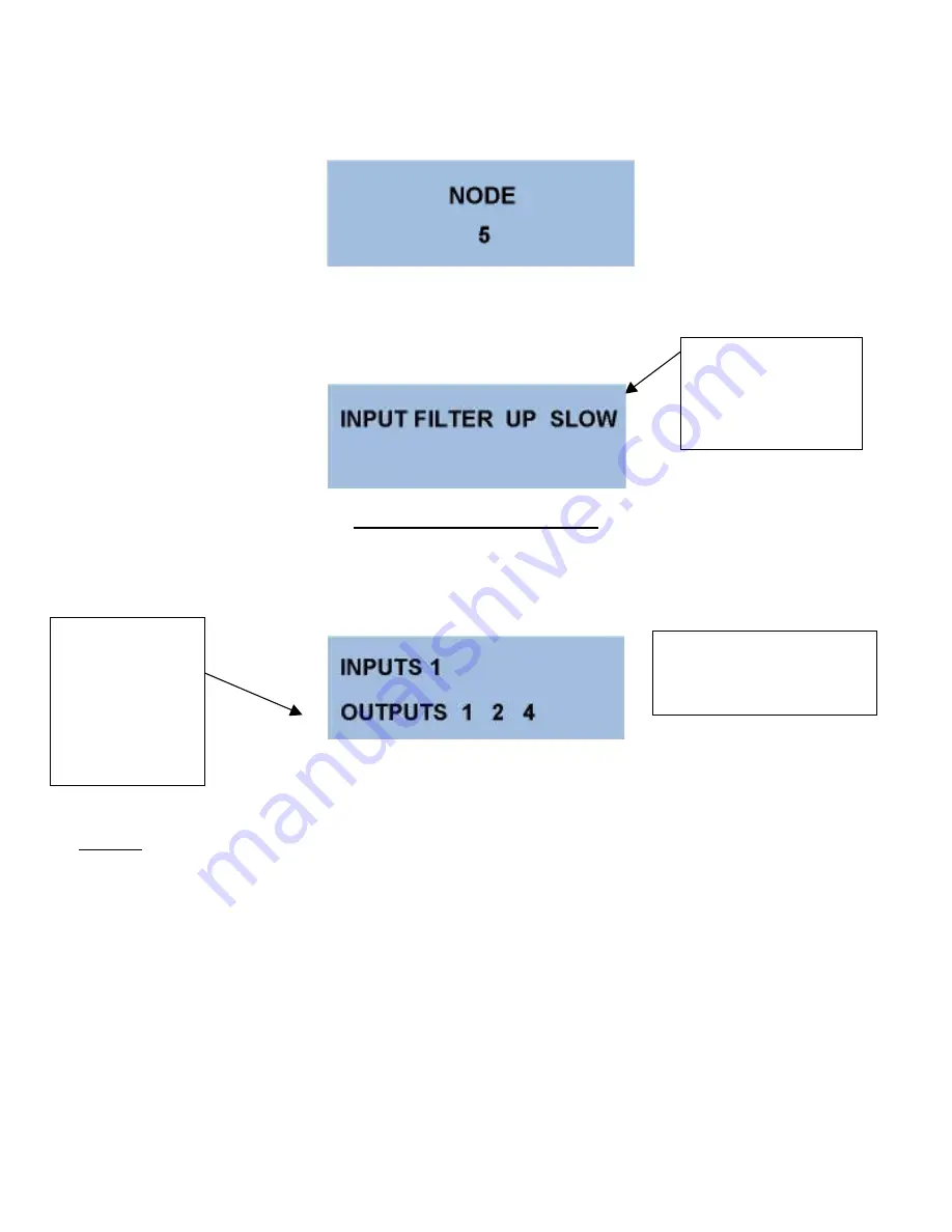
to advance to the NODE screen. This allows selection of the unit NODE number when used in
MODBUS
Network.
Press
to advance to the input filter screen.
THE DIAGNOSTIC SCREEN
The final menu item is ‘DIAGNOSTICS’. This screen provides real time information about the current
status of both inputs and outputs.
NOTE:
Only digital input (1) is used in the 700MM.
This is the Relay
Output status.
Shown is Relay
1 and Relay 2
Active. The 8
inputs are shown
the same way.
NOTE:
Use the
input filter to
“dampen” noisy or
bouncing values.
NOTE:
No relays in
Data logger.
Summary of Contents for 700 PDL Series
Page 6: ...6...


