background image


C-DIAS IPC WITH AMD FUSION G-T56N 

C-IPC 171 


04.11.2019 

Page 31 

Cooling 

The  terminal's  power  loss can  reach up to 45 Watts.  The  built-in  fan  removes most of  the 
generated heat. Also when mounted, heat dissipation must be ensured. 


At processor temperatures above the allowed limit, the C-IPC will shut down auto-

matically! 

The C-IPC will only resume normal operation after a sufficient cooling period (1 minute). 

After an emergency shutdown, the fan function and environmental conditions should be 

checked. 


System Boot Checkpoints 

The  checkpoints  are  shown  on  the  7-segment  display  before  the  LASAL  CLASS  software 
status and error messages. Since these involve checkpoints, they are to be interpreted as 
errors when the system stops at one of the checkpoints. 
 

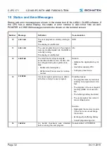
Number 

Definition 

Cause/solution 

FF 

The operating system or the application 
cannot be started. 

-  Check operating system/boot medium 

- Boot medium not plugged in 
- Boot medium defective 
- No operating system on the boot medium  


Summary of Contents for C-IPC 171

Page 1: ...C IPC 171 C DIAS IPC with AMD Fusion G T56N Date of creation 27 07 2017 Version date 04 11 2019 Article number 01 450 171 E ...

Page 2: ...rt of this work may be reproduced edited using an electronic system duplicated or dis tributed in any form print photocopy microfilm or in any other process without the express permission We reserve the right to make changes in the content without notice The SIGMATEK GmbH Co KG is not responsi ble for technical or printing errors in the handbook and assumes no responsibility for damages that occur...

Page 3: ... 3 status LEDs provide infor mation on the actual status of the CPU A CompactFlash card can be used as program memory The C IPC also has an VGA interface for a display and a USB V1 1 interface In addition an expansion card with further interface connections is available Compatibility Completely PC compatible The C IPC works with a standard PC BIOS no SIGMATEK specific BIOS is therefore needed LASA...

Page 4: ...ironmental Conditions 6 1 6 Xilinx Version 7 1 7 Post Codes 7 2 Mechanical Dimensions 8 3 Connector Layout 9 3 1 Connector Layout 10 3 2 Applicable Connectors 13 3 3 Bottom Connectors 14 4 Status Displays 15 5 Setting C IPC Parameters with the SET Button under LASAL operating system only 16 6 Design Layout 19 6 1 Exchanging the CompactFlash Card 22 6 2 Storage Media 23 6 3 Exchanging the Battery 2...

Page 5: ...e 3 6 4 CAN Bus Termination 25 6 5 RS485 26 6 6 USB Interface Connections 27 6 7 DIAS Bus Termination 27 6 8 The DIAS Bus Connection 27 6 9 Connecting DIAS Modules 29 7 Buffer Battery 30 8 Cooling 31 9 System Boot Checkpoints 31 10 Status and Error Messages 32 ...

Page 6: ...0 100 Mbit 1x RS 232 COM1 1x RS232 RS485 RS422 COM2 1x DIAS intelligent Weidmüller plug and 14 Pin ribbon cable 1x CAN for PLC 1x CAN for a Terminal 1x VGA 1x S DVI interface for a 15 terminal TFT display USB CAN key board Resolution 1024 x 768 pixels 1x USV 1x USB V1 1 Interfaces via expansion cards optional 1x VARAN maximum cable length 100 m 1x Ethernet 10 100 1x LPT Printer 1x RS232 RS485 RS42...

Page 7: ... the packet filter Firewall or Router accordingly however it is possible to connect a network with SIGMATEK hardware to a third party network without trig gering the error mentioned above 1 3 Electrical Requirements Supply voltage 18 30 V DC 1 typically 24 V DC UL Class 2 or LVLC 3 Current consumption of the power supply 24 V maximum 3 2 A depending on external devices Inrush current maximum 9 A f...

Page 8: ...DDR3 RAM 1x 512 MB CompactFlash 01 450 171 TC IPC 171 1 GB Fusion T56N 1 GB DDR3 RAM 1x 512 MB CompactFlash with Coating of the electronic 01 450 171 T Module identification on DIAS bus no Hardware Version 1 x Project backup internally on CompactFlash Standard UL 508 E247993 Approvals CULUS listed CE 1 5 Environmental Conditions Storage temperature 20 85 C Ambient temperature 5 50 C Max Process te...

Page 9: ...s shown in the display In display D1 43 is shown and in display 41 the version number can be seen This infor mation can also be found on the identification label e g X 1 8 1 7 Post Codes During startup the BIOS dependent post codes are shown in the display It is important to note these codes in order to simplify troubleshooting if an error occurs ...

Page 10: ...C IPC 171 C DIAS IPC WITH AMD FUSION G T56N Page 8 04 11 2019 2 Mechanical Dimensions ...

Page 11: ...C DIAS IPC WITH AMD FUSION G T56N C IPC 171 04 11 2019 Page 9 3 Connector Layout ...

Page 12: ...2 RTS 3 TxD 4 CTS 5 DTR 6 GND 7 DCD 8 DSR 9 RI 10 n c Pin Function RS232 Function RS422 Function RS485 1 RxD RS422 TxD RS485 A 2 RTS RS422 TxD RS485 B 3 TxD RS422 RxD n c 4 CTS RS422 RxD n c 5 DTR n c n c 6 GND GND GND 7 n c RS422 TxD RS485 A 8 n c RS422 TxD RS485 B 9 n c RS422 RxD n c 10 n c RS422 RxD n c Pin Function 1 CAN SA LOW 2 CAN SB HIGH 3 CAN SA LOW 4 CAN SB HIGH 5 GND 6 5 V for online ad...

Page 13: ...Pin Function 1 CAN A LOW 2 CAN B HIGH 3 CAN A LOW 4 CAN B HIGH 5 GND 6 n c Pin Function 1 MBUS 2 MBUS 3 SBUS 4 SBUS 5 GND 6 n c Pin Function 1 5 V 2 D0 3 D0 4 GND Pin Function Pin Function 1 DVI1 14 Shielded 2 DVI1 15 Shielded 3 DVI2 16 Shielded 4 DVI2 17 Shielded 5 DVI3 18 Shielded 6 DVI3 19 24 V 7 DVIC 20 24 V 8 DVIC 21 USB Ext In 9 Reserved 22 USB Ext In 10 GND 23 USB Ext Out 11 GND 24 USB Ext ...

Page 14: ... has been connected Otherwise a video signal will not be sent to this interface X10 Power Supply 24 30 Volt DC 2 pin Phoenix 3 5 mm power supply X11 External UPS Connection 6 pin Phoenix 3 5 mm UPS Pin Function 1 TD 2 TD 3 RD 4 n c 5 n c 6 RD 7 n c 8 n c Pin Function 1 red 2 GND 3 green 4 GND 5 blue 6 GND 7 Vsync 8 GND 9 Hsync 10 GND Pin Function 1 24 V 2 GND Pin Function 1 RxD 2 TxD 3 RTS USV Off...

Page 15: ... 2 ST 3 5 USV 6 pin Phoenix FK MCP 1 5 6 ST 3 5 The complete C DIAS CKL 012 connector set with spring terminals is available from SIGMATEK under the article number 12 600 012 S DVI Cable 0 3 m 2 m 3 m 3 5 5 m 7 m 10 m 15 m Art No 05 950 003 Art No 05 950 020 Art No 05 950 030 Art No 05 950 035 Art No 05 950 050 Art No 05 950 070 Art No 05 950 100 Art No 05 950 150 NOTE Connecting the S DVI cable u...

Page 16: ...the C IPC a DIAS power module power booster between the C IPC and DIAS module is required The measure is necessary to protect the C IPC from EMC noise and to unburden the DCDC converter in the C IPC reducing power loss in the C IPC Pin Function 1 GND 2 MBUS 3 MBUS 4 GND 5 SBUS 6 SBUS 7 GND 8 DCOK 9 13 5 V 14 GND Connection to the C IPC X13 Connection to the 1st DIAS module DPB 002 05 002 002l ...

Page 17: ...ge 15 4 Status Displays LED 1 Green DC OK Lights when the supply voltage is correct LED 2 Green Run Lights when the program is running LED 3 Red Error Lights when an error occurs Button 1 Set Set display Ethernet CAN address Button 2 Reset Reset CPU hardware ...

Page 18: ...ing the various settings can be viewed by quickly pressing the set button multiple times To change between the setting and the value the Set button must be pressed for about 1 5 s Once the desired changes are made press the SET button for about 5 seconds to end the process If the changes are to be discarded press the RESET button to restart the C IPC The settings for the IP address subnet mask and...

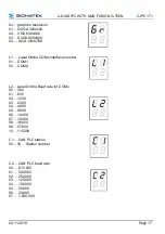
Page 19: ...A 1024x768 L1 Lasal Online COMx interface number 01 COM1 02 COM2 L2 Lasal Online Baud rate for COMx 00 300 01 600 02 1200 03 2400 04 4800 05 9600 06 14400 07 19200 08 38400 09 57600 10 115200 C1 CAN PLC station 00 30 Station number C2 CAN PLC baud rate 00 615 000 01 500 000 02 250 000 03 125 000 04 100 000 05 50 000 06 20 000 07 1 000 000 ...

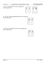
Page 20: ... FUSION G T56N Page 18 04 11 2019 I1 I2 I3 I4 IP Address I1 I2 I3 I4 hexadecimal 00 FF respectively S1 S2 SI3 S4 Subnet Mask SI1SI2 S3 S4 hexadecimal 00 FF respectively G1 G2 G3 G4 Gateway G1 G2 G3 G4 hexadecimal 00 FF respectively ...

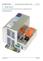
Page 21: ...C DIAS IPC WITH AMD FUSION G T56N C IPC 171 04 11 2019 Page 19 6 Design Layout The CPU module is placed on the left side of the C DIAS module carrier Front view with cover ...

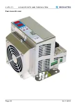
Page 22: ...C IPC 171 C DIAS IPC WITH AMD FUSION G T56N Page 20 04 11 2019 Rear view with cover ...

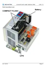
Page 23: ...C DIAS IPC WITH AMD FUSION G T56N C IPC 171 04 11 2019 Page 21 Front view without cover Battery UPS ...

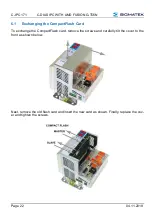
Page 24: ...19 6 1 Exchanging the CompactFlash Card To exchange the CompactFlash card remove the screws and carefully tilt the cover to the front as shown below Next remove the old flash card and insert the new card as shown Finally replace the cov er and tighten the screws ...

Page 25: ...card in the master slot is always the primary BOOT device 6 2 Storage Media It is recommended that only storage media provided by SIGMATEK CompactFlash cards microSD cards etc be used The number of read and write actions have a significant influence on the lifespan of the storage media ...

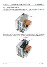
Page 26: ...be exchanged when the C IPC is OFF To exchange the battery re move the screws and carefully tilt the cover to the front as shown below Next remove the old battery from the fixture and insert the new one When inserting the new battery ensure the polarity is correct Finally replace the cover and tighten the screws ...

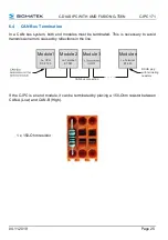
Page 27: ...necessary to avoid transmission errors caused by reflections in the line Module1 Module 2 Module 3 Module n I e CPU DCP 160 I e Terminal ET 081 CAN bus connection DSUB plug with terimating resistors I e Terminal ET 805 If the C IPC is an end module it can be terminated by placing a 150 Ohm resistor between CAN A Low and CAN B High 1 x 150 Ohm resistor ...

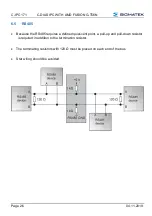
Page 28: ... 2019 6 5 RS485 Because the RS485 requires a defined quiescent point a pull up and pull down resistor is required in addition to the termination resistor The terminating resistors with 120 Ω must be placed on each end of the bus Star wiring should be avoided ...

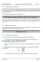
Page 29: ...cting such a device can lead to malfunc tions 6 7 DIAS Bus Termination In a DIAS bus system both end modules must be terminated This is necessary to avoid transmission errors caused by reflections in the line The DIAS bus termination is integrated in the C IPC and must no longer be built into the DIAS bus connector 6 8 The DIAS Bus Connection To ensure a good bus connection several wiring guidelin...

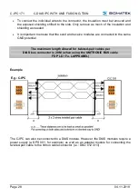
Page 30: ...o ensure that the send and receive modules are connected to the same GND potential The maximum length allowed for twisted pair cables per DIAS bus connector is 20 M when using the UNITRONIC BUS cable FD P LD Fa LAPPKABEL Example The C IPC can also be connected to a DIAS module However the DIAS modules require a power supply a DPS 001 for example as well as an adapter module for connecting the twis...

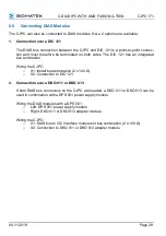
Page 31: ...as an integrated bus termination Wiring the C IPC o X1 Install bus termination 2 x 100 Ω o X2 Connection to DIC 121 2 Connection over a DKO 011 or DKO 013 If both DIAS bus connectors on the C IPC are needed a DKO 011 or DKO 013 can be used in combination with a DPS 001 power supply module Wiring the DIAS modules with a DPS 001 o Left DPS 001 power supply module o Right DKO 011 or DKO 013 adapter m...

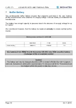
Page 32: ...oltage for up to 3 years We recommend however that the battery be replaced annually to ensure optimal perfor mance Battery order number 01 690 028 COMPANY TYPE DATA Lithium battery RENATA CR2032 3 V Use batteries from RENATA with the number CR2032 only With any other battery the danger of fire or explosion exists Caution The battery can only be changed when the C IPC is turned off After the 24 V s...

Page 33: ...ooling period 1 minute After an emergency shutdown the fan function and environmental conditions should be checked 9 System Boot Checkpoints The checkpoints are shown on the 7 segment display before the LASAL CLASS software status and error messages Since these involve checkpoints they are to be interpreted as errors when the system stops at one of the checkpoints Number Definition Cause solution ...

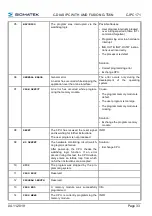
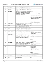
Page 34: ...al time for all cyclic objects exceed the maximum time the time can be configured using two system varia bles Runtime Remaining time SWRuntime Preset value for runtime counter Solution Optimize the application s cyclic task Use higher capacity CPU Configure preset value 03 POINTER Incorrect program pointers were detect ed before running the user program Possible Causes The program memory module is...

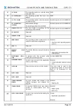
Page 35: ...ng the memory module Cause The program memory module is defect The user program is too large The program memory module is missing Solution Exchange the program memory module 08 RESET The CPU has received the reset signal and is waiting for further instructions The user program is not processed INFO 09 WD DEFEKT The hardware monitoring circuit watch dog logic is defective After power up the CPU che...

Page 36: ...am INFO 20 LOAD The program is stopped and the CPU is currently receiving a new module or project INFO 21 UNZUL MODULE The CPU has received a module that does not belong to the project Solution Recompile and download the entire project 22 MEMORY FULL The operating system memory Heap is too small No memory could be reserved while calling an internal or interface function is called from the applicat...

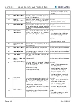
Page 37: ... IO Reserved 36 MODULE LOAD ERROR The LASAL Module or project cannot be loaded Solution Recompile and download the entire project 37 BOOTIMAGE FAIL URE A general error has occurred while loading the operating system Contact SIGMATEK 38 APPLMEM ERROR An error has occurred in the application memory user heap Solution Correct allocated memory access error 39 OFFLINE This error does not occur in the c...

Page 38: ...eport error to SIGMATEK 64 INTERNAL ERROR An internal error has occurred all appli cations are stopped Restart report error to SIGMATEK 65 FILE ERROR An error has occurred during a file operation 66 DEBUG ASSERTION FAILED Internal error Restart report error to SIGMATEK 67 REALTIME RUNTIME The total duration of all real time objects exceeds the maximum time the time cannot be configured 2 ms for 38...

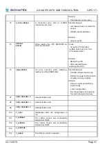
Page 39: ...nge the CPU 75 SRAM ERROR An error occurred while initializing reading or writing SRAM data Possible Causes SRAM configured incorrectly Battery for powering the internal program memory is empty Solution Analyze log file Event00 log Event19 log check configuration Exchange battery for powering the internal program memory 97 USER DEFINED 2 User definable code 98 USER DEFINED 3 User definable code 99...

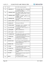
Page 40: ... 113 C_NO_FILE_OPEN An attempt was made to open an un known table 114 C_OUTOF_NEAR Memory allocation error 115 C_OUT OF_FAR Memory allocation error 116 C_INCOMAPTIBLE An object with the same name already exists but has a different class 117 C_COMPATIBLE An object with the same name and class exists but must be updated 224 LINKING The application is currently linking 225 LINKING ERROR An error has ...

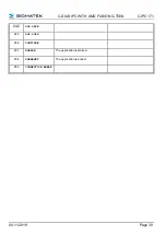
Page 41: ...C DIAS IPC WITH AMD FUSION G T56N C IPC 171 04 11 2019 Page 39 242 LSL SAVE 243 LSL LOAD 252 CONTINUE 253 PRERUN The application is started 254 PRERESET The application is ended 255 CONNECTION BREAK ...

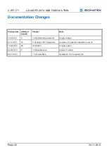
Page 42: ...cted page s Chapter Note 19 10 2017 5 1 3 Electrical Requirements Supply voltage 21 11 2017 16 5 Setting C IPC Parameters Sentence for graphics resolution removed 15 03 2018 26 6 5 RS485 Chapter added 24 06 2019 6 1 4 Miscellaneous Variant T added 04 11 2019 1 Technical Data Updated to TÜV requirements ...

Reviews: