C-DIAS IPC WITH AMD FUSION G-T56N
C-IPC 171
04.11.2019
Page 27
6.6
USB Interface Connections
The C-IPC control panel has a USB interface. The terminal has a USB interface connection
that can be used to connect various USB devices (keyboard, mouse, storage media, hubs,
etc.) in LASAL. Using a hub, several USB devices can be connected that are then fully
functional in LASAL.
The following restriction applies to the BIOS setup:
The BIOS setup can only be accessed when the USB keyboard is connected directly
to the USB socket.
Using a USB hub can cause errors in the BIOS setup!
It should be noted that many USB devices on the market do not comply with the relevant
EMC standards for industrial environments. Connecting such a device can lead to malfunc-
tions.
6.7
DIAS Bus Termination
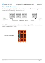
In a DIAS bus system, both end modules must be terminated. This is necessary to avoid
transmission errors caused by reflections in the line.
The DIAS bus termination is integrated in the C-IPC and must no longer be built into
the DIAS bus connector.
6.8
The DIAS Bus Connection
To ensure a good bus connection, several wiring guidelines must be followed:
•
It is important to ensure the cables used are designed for the data transfer speed.
Data cables (10Mbit, 2 x 2 wire TWISTED PAIR, shielded)
e.g.: LAPPKABEL / UNITRONIC-BUSLEITUNG FD P LD
•
Because of the internal resistance of the module, the cable impedance should be 100
Ohms.
•
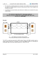
With twisted-pair cables, ensure that the correct pairs are connected to one another:
2x2 pair cables:
Pair 1
MBUS+
MBUS-
Pair 2
SBUS+
SBUS-
•
The shielding must be connected over a large area and the shortest possible route.

