background image

CCP 621 

C-DIAS PROSESSOR MODULE


Page 10  

27.03.2020 

Connector Layout 


Summary of Contents for CCP 621

Page 1: ...CCP 621 C DIAS Processor Module Date of creation 26 11 2013 Version date 27 03 2020 Article number 13 104 621 E...

Page 2: ...of this work may be reproduced edited using an electronic system duplicated or dis tributed in any form print photocopy microfilm or in any other process without the express permission We reserve the...

Page 3: ...atus of the CPU For program updates the integrated USB host interface can be used USB stick keyboard With help from the exchange able microSD card the entire control program can be easily exchanged Th...

Page 4: ...llaneous 7 1 5 Environmental Conditions 7 2 Mechanical Dimensions 8 3 Mounting position 9 4 Connector Layout 10 4 1 Applicable Connectors 13 5 Exchanging the microSD Card 15 6 Status Displays 16 7 Dis...

Page 5: ...am 26 14 System Boot Checkpoints 27 15 Status and Error Messages 28 16 Application Exceptions 36 16 1 SRAM and IRQ routines 36 16 2 SRAM and Consistency of Changed Data 36 16 3 The File System Does No...

Page 6: ...CCP 621 C DIAS PROSESSOR MODULE Page 4 27 03 2020 18 3 Shielding for Wiring Within the Control Cabinet 41 18 4 Connecting Noise Generating Components 42 18 5 Shielding Between Two Control Cabinets 43...

Page 7: ...OS AMI Internal program and data memory DDR2 RAM 128 Mbyte Internal remnant data memory 512 kbyte 1 Internal storage device 512 Mbyte microSD card Interfaces 1x USB Host 2 0 full speed 12 Mbit s 1x US...

Page 8: ...un on a SIGMATEK operating system With such devices Ethernet packets could be sent to the control with such a high frequency i e broadcasts that the high interrupt load could cause a real time runtime...

Page 9: ...up internally on the microSD card Standard UL 508 E247993 Approbations cUL UL 1 5 Environmental Conditions Storage temperature 10 85 C Environmental temperature 0 45 C Humidity 10 90 non condensing EM...

Page 10: ...CCP 621 C DIAS PROSESSOR MODULE Page 8 27 03 2020 2 Mechanical Dimensions...

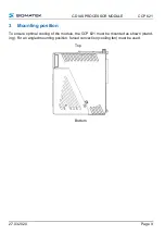
Page 11: ...LE CCP 621 27 03 2020 Page 9 3 Mounting position To ensure optimal cooling of the module the CCP 621 must be mounted as shown stand ing For an angled mounting position forced convection cooling fan mu...

Page 12: ...CCP 621 C DIAS PROSESSOR MODULE Page 10 27 03 2020 4 Connector Layout...

Page 13: ...iph riques USB sur le march ne sont pas conformes aux sp cifications USB ce qui peut entra ner des dysfonctionnements de l appareil Il est galement possible que ces dispositifs ne seront pas d tect s...

Page 14: ...High 5 GND 6 n c Pin Function Pin Function 1 DVI1 14 Shielded 2 DVI1 15 Shielded 3 DVI2 16 Shielded 4 DVI2 17 Shielded 5 DVI3 18 Shielded 6 DVI3 19 24 V 7 DVIC 20 24 V 8 DVIC 21 USB Ext In 9 Reserved...

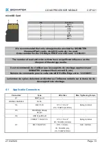
Page 15: ...t flash microSD etc Num ro de commande pour la carte microSD 512 Mo Edge est le 12 630 051 Le nombre de cycles de lecture et d criture a l influence notable sur la dur e de vie des supports de stockag...

Page 16: ...Phoenix plug with spring terminal FK MCP 1 5 2 ST 3 5 The complete C DIAS CKL 031 connector set with spring terminals is available from SIGMATEK under the article number 12 600 017 S DVI Cable 0 3 m...

Page 17: ...nging the microSD Card The microSD card is located under the LED cover To exchange the microSD card carefully lift the LED cover The microSD card is located on the left side and can be disengaged by l...

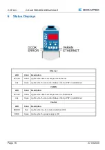
Page 18: ...Green Lights when the connection between the two PHYs is established VARAN LED Color Description ACTIVE Yellow Lights when data is exchanged over the VARAN bus Link Green Lights when the connection b...

Page 19: ...isplay If an error occurs while running the program or no valid user program is found the dis play shows an error message Er error and the error code thereby alternate in the display The same error co...

Page 20: ...mber of participants on the CAN bus depends on the cable length termi nation resistance data transfer rate and the drivers used in the participants With a termination resistance of 120 at least 100 pa...

Page 21: ...C DIAS PROCESSOR MODULE CCP 621 27 03 2020 Page 19 9 Configuration of the Process Module...

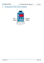
Page 22: ...1 5 s the menu opens and the settings can be made with a series of short presses Once the desired changes are made press the SET button for about 5 seconds to end the process If the changes are to be...

Page 23: ...ber C2 CAN PLC baud rate 00 615 000 01 500 000 02 250 000 03 125 000 04 100 000 05 50 000 06 20 000 07 1 000 000 I1 I2 I3 I4 IP address I1 I2 I3 I4 Hexadecimal 00 FF each S1 S2 S3 S4 Subnet Mask S1 S2...

Page 24: ...bus system both end modules must be terminated This is necessary to avoid transmission errors caused by reflections in the line If the CCP 621 processor module is an end module it can be terminated b...

Page 25: ...rovided C DIAS module carrier It is important to create a low ohm ground connection only then can error free operation be guaranteed The ground connection should have a maximum cross section and the l...

Page 26: ...CP 621 processor module over a large surface cable grommets grounding clamps Noise signals can therefore be prevented from reaching the electronics and affecting the function 11 3 ESD Protection Befor...

Page 27: ...CCP 621 The applicable operating safety guidelines for personal safety must be observed During installation initial start up maintenance of the product appropriate ESD pro tection measures must be ta...

Page 28: ...CCP 621 C DIAS PROSESSOR MODULE Page 26 27 03 2020 13 Process Diagram...

Page 29: ...erpreted as errors when the system stops at a checkpoint Number Meaning Cause solution 88 Display during system start If the status does not change the operating system or application cannot be starte...

Page 30: ...currently running The display is not affected 02 RUNTIME The total time for all cyclic objects exceed the maximum time the time can be configured using two system variables Runtime time remaining SWRu...

Page 31: ...memory module is defect The user program is too large The program memory module is missing Solution Exchange the program memory module 08 RESET The CPU has received the reset signal and is waiting for...

Page 32: ...in single step mode and is waiting for further instructions 19 READY A module or project has been sent to the CPU and it is ready to run the program 20 LOAD The program is stopped and the CPU is curre...

Page 33: ...9 OS TOO LONG The operating system cannot be loaded too little memory 30 NO OPERATING SYSTEM Boot loader message No operating system found in RAM 31 SEARCH FOR OS The boot loader is searching for the...

Page 34: ...rite access to prohibited memory area e g writing to NULL pointer 51 BOUND EXCEEDED An exception error caused by exceeding the memory limits 52 PRIVILEDGED INSTRUCTION An unauthorized instruction for...

Page 35: ...module has occurred Possible causes real network does not match the project S DIAS client is defective Solution analyze logfile 75 SRAM ERROR Only EDGE CPUs An error occurred while initializing readi...

Page 36: ...ne DCC080 object 109 C_UNKNOWN_CHNL The hardware module number is greater than 60 110 C_WRONG_CONNECT No connection to the required channels 111 C_WRONG_ATTR Wrong server attributes 112 C_SYNTAX_ERROR...

Page 37: ...red while burning the operating system 232 OP INSTALL The operating system is currently being installed 240 USV WAIT The power supply was disconnect ed the UPS is active 241 REBOOT The operating syste...

Page 38: ...ply while the user program is writing to the microSD card this can some times lead to partial loss of remnant data 16 3 The File System Does Not Support Safe Writing via SRAM If files are stored modif...

Page 39: ...e user program can have a massive effect on the microSD card lifespan Detailed information regarding the SRAM behavior and the corresponding settings can be found in the LASAL OS documentation in the...

Page 40: ...ld ing is required This is especially important if due to physical requirements the bus cables must be placed next to sources of strong electromagnetic noise It is recommended to avoid placing VARAN b...

Page 41: ...al VARAN component If the Ethernet lines are connected from a VARAN component to a VARAN node located outside the control cabinet the shielding should be placed at the entry point to the control cabin...

Page 42: ...no additional shield support is required A requirement therefore is that only IP67 modules and connect ors can be used outside the control cabinet These components are very robust and noise resistant...

Page 43: ...ers etc can induce interference in a VARAN bus line Spike voltages are dissipated over the metallic housing of a RJ45 connector Noise is conducted through the control cabi net housing without further...

Page 44: ...onnecting Noise Generating Components With the connection of power components that generate strong electromagnetic interfer ence it is also critical to ensure correct shielding The shielding should be...

Page 45: ...ng Between Two Control Cabinets If two control cabinets must be connected over a VARAN bus it is recommended that the shielding be located at the entry points of both cabinets Noise can be thereby pre...

Page 46: ...er of CAN Bus Participants Changed text Changed text 10 06 2014 29 13 Status and Error Mes sages S DIAS Error added 31 03 2015 11 3 Connector Layout Added microSD Card 19 08 2015 24 13 System Boot Che...

Reviews: