-8-
ELECTRICAL CONNECTIONS
AMPLIFIER
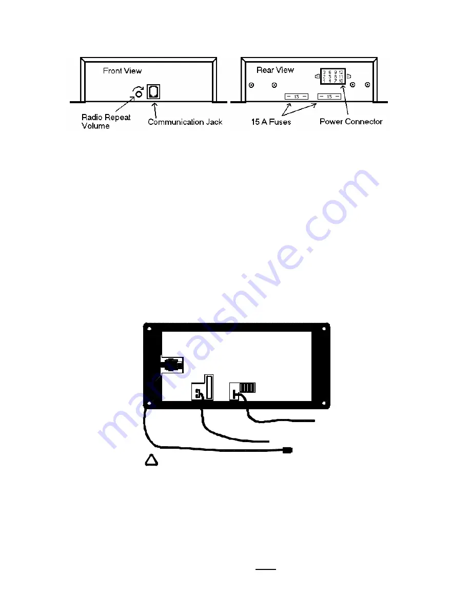
Electrical power connections to the amplifier are made using a removable
connector located on the back of the amplifier case. Communication between the
control head and the amplifier are made via a special communication cable.
CAUTION: Please note that this cable IS NOT a standard telephone cord and
CANNOT be replaced with one.
You should make all electrical connections to
the power connector before installing the connector on the unit. If the unit needs
service, both the communication cable and the power connector can be easily
removed without unwiring the connector.
The power supply of the unit must be capable of delivering peak currents up
to 50 amps for adequate short circuit protection and reliable operation. The
preferred source is directly at the vehicle battery. The unit is internally fused.
The wiring diagram page 10 shows detail of how to wire the power connector on
the amplifier to the vehicle.
CONTROL HEAD
Electrical power connections to the control head are made using one male
and one female spade terminal. The black wire included in the kit with the
female terminal should be plugged into the male spade terminal on the back of the
control head. The red wire included in the kit with the male terminal should be
plugged into the female terminal on the back of the control head. Commu nication
between the control head and the amplifier is made via a communication cable
with an RJ11 connector at both ends. The communication cable should have one
end plugged into the amplifier (RJ11 jack) and the other end plugged into the
control head (RJ11 jack).
Please Note: This is NOT a standard telephone cable.
- 5 -
Communication
Cable (w/RJ11 jacks)
Red: +12VDC
Black: GROUND
!
CAUTION: NOT REPLACEABLE WITH A
STANDARD TELEPHONE CABLE
Rear of SS741 Control Head


