SC5312A Operating & Programming Manual
Rev 1.0.2
6
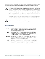
All RF signal connections (ports) on the SC5312A are SMA-type. Exercise caution when fastening cables to
the signal connections. Over-tightening any connection can cause permanent damage to the device.
The condition of
your system‘s signal connections can significa
ntly affect measurement
accuracy and repeatability. Improperly mated connections or dirty, damaged or worn
connectors can degrade measurement performance. Clean out any loose, dry debris from
connectors with clean, low-pressure air (available in spray cans from office supply stores).
If deeper cleaning is necessary, use lint-free swabs and isopropyl alcohol to gently clean inside
the connector barrel and the external threads. Do not mate connectors until the alcohol has
completely evaporated. Excess liquid alcohol trapped inside the connector may take several
days to fully evaporate and may degrade measurement performance until fully evaporated.
Tighten all SMA connections to 5 in-lb max (56 N-cm max)
RF Signal Connections
LO OUT
This port outputs the tunable LO signal allowing phase-coherent daisy-
chaining of multiple IQ demodulator modules. The connector is SMA female.
The nominal output impedance is 50 Ω.
RF IN
This port accepts an RF signal ranging from 400 MHz to 6 GHz. The connector
is SMA female. The nominal input
impedance is 50 Ω.
Maximum input power
is +23 dBm with ATTEN #1 set to at least 10 dB attenuation.
RF AUX IN
This port accepts an RF signal ranging from 400 MHz to 6 GHz. This port can
be used as an alternate path for system-level calibration. The connector is
SMA female. The nominal input
impedance is 50 Ω.
LO IN
This port accepts a tunable LO signal from an external source to drive the
demodulator. The connector is SMA female. This port is AC-coupled with a
nominal input impedance of
50 Ω. Maximum input power is +10
dBm.
!
!


