


above the booster gain.
When self-
oscillation occurs, the alarm LED, “AGC Alarm” will be flashing.
Booster
may be damaged if it operates under self-oscillation condition.
3.2.3.2 Obtaining the Isolation Value
Theoretical calculation (for reference only)
The physical isolation between the donor and the service antennas can be
theoretically estimated using the following formulas.
I
=
Isolation
D
=
Distance between donor and service antennas (m)
λ
=
Wavelength (m)
G
d
=
Gain of donor antenna facing service antenna
G
s
=
Gain of service antenna facing donor antenna
If there is an obstacle (wall etc.) between donor and service antenna, the
attenuation value of the obstacle need be added into the equation.
Physical Test
To obtain an accurate and more precise estimation of the isolation value, a
physical measurement may be carried out to obtain the isolation value for the
actually environment where the booster is installed. The measurement
procedures are:
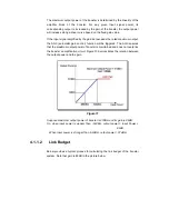
Connect a signal generator to the donor antenna cable as illustrated
below and transmit a known frequency and power level from the signal
generator. Frequency needs to be within the idle frequency between the
uplink and the downlink frequencies.
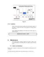
For example, in GSM 900 system, uplink is 890~915MHz and downlink is
935~960MHz. We can use the frequency 920MHz, which is within
915MHz and 935MHz, to do the measurement. In DCS 1800 system, the
uplink is from 1710~1785MHz and the downlink is from 1805~1880MHz.
The idle frequency 1795MHz can be used to do the measurement.
Connect the service antenna to a spectrum analyzer and scan for the
known frequency.
Isol
ation ≥ Gain of B 15dB
Vertical Isolation: I (dB) = 28 + 40 log (D/λ)
Horizontal Isolation: I (dB) = 22 + 20 log (D/λ) – (G
d
+ G
s
)


