


environment.
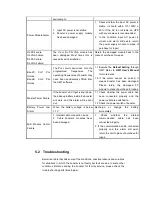
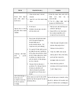
Power Module Alarm
1. Input AC power is not stable.
2. Booster
’s power supply module
has been damaged
1. Check whether the input AC power is
stable, it should within 110/ 220V ±
20%. If the AC is not stable, an UPS
with square wave is recommended.
2. In the condition input AC power is
correct and alarm still exists, return
the power supply module to place of
purchase for repair.
UL PA Failure
UL LNA Failure
DL PA Failure
DL LNA Failure
The UL or DL PA/ LNA module has
been damaged. Most times this is
caused by self-osciallation.
Return the damaged module back to the
place of purchase for repair.
Band1/
CH1
PLL
Unlock
Band2/
CH2
PLL
Unlock
The PLL circuit cannot lock onto the
programmed
frequencies.
The
operating frequencies of booster may
have been accidentally shifted from
the OMT software.
1.1 Execute the
Default Setting
through
OMT. Refer to
OMT User’s Manual
for more detail.
1.2 If the alarm cannot be solved, it
means booster has been damaged.
Please return the damaged FC
module to place of purchase for repair.
Master Power Failure
If the booster
’s AC input is shut down,
the back-up battery inside the booster
will work, and this alarm will be sent
out.
1.1 Check whether the power cable has
been connected properly and the
power outlet are switched on.
1.2 Check the power switch of booster.
Battery Power Low
Alarm
When the battery voltage is below
7.7V.
Recharge
or
change
the
battery
immediately
M/S Module Comm.
Failure
1. Internal cable connection loose
2. Cable booster’s modules have
been damaged
1.
Check
whether
the
internal
communication
cable
has
been
connected properly
2. If the communication cable connected
properly and this alarm still exist,
return the unit to place of purchase for
repair.
5.2 Troubleshooting
Below is a table that lists some of the conditions, possible reasons and solutions
for situations in which the booster is not faulty but fault are due to some other
conditions. Before sending the booster for factory service, please check the
trouble shooting parts listed below.


