


Fast & easy Installation
Compared to the Base Station, wireless boosters is space saving and does not
need additional wiring. Its installation simplicity and operational user friendliness
appeal greatly to many operators for the purpose of rural coverage or use of
temporary coverage during network optimization.
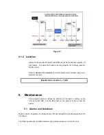
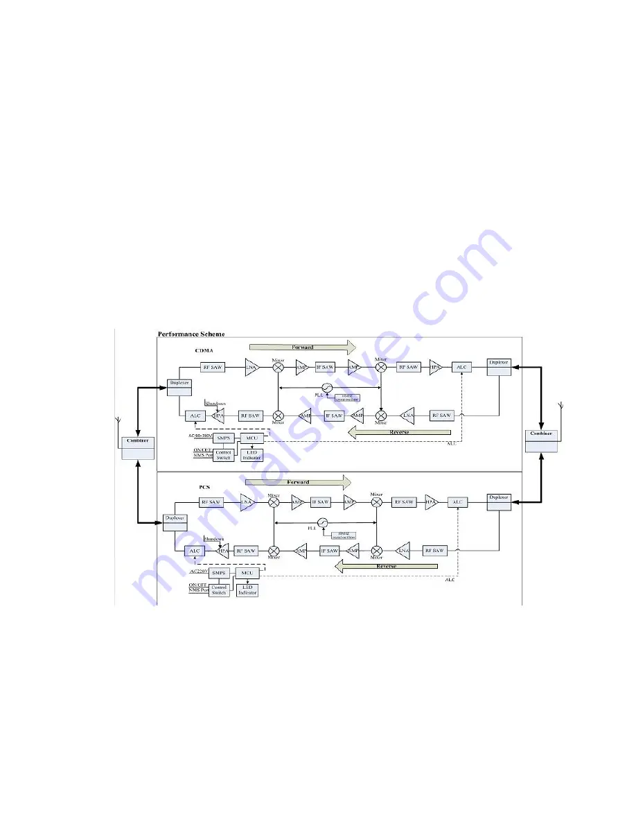
2.5 Block Diagram
The booster has two similar circuits, which are designed for uplink and
downlink respectively. Each circuit consists of three main modules, the Low
Noise Amplifier (LNA), the Frequency Converter (FC), and the Power
Amplifier (PA).
Let’s just consider the downlink part first, which is from BTS to MS. Please note
that uplink works in the same way except the signal direction is from MS to BTS.
Figure 4 illustrates the self-explanatory signal path after entering into the
booster.
Figure 4 Dual Band Selective Booster
When uplink or downlink signal enters the booster, it is filtered by duplexer
firstly. Then the filtered signal enters into LNA in which weak signals are
amplified with low noise figure. Then the signal passes FC where signal
frequency is made to IF to have a good filtration after passing through SAW
filter in the FC. Through module FC, operator’s signals are selected while the
competitors’ signals are strongly rejected. At last the signals are amplified in
power amplifier (PA) and are sent to service antenna.


