background image

Signamax

 065-1140 series and 065-1150 series  

10BaseT to 10BaseFL Converter


FCC Warning 


This equipment has been tested and found to comply with 
the limits for a class A digital device, pursuant to Part 15 of 
the  FCC  Rules. These limits are designed to provide 
reasonable protection against  harmful interference when 
the equipment is operated in a commercial environment. 
This equipment generates, uses and can radiate radio 
frequency energy  and, if not installed and used in 
accordance with  this user’s guide, may cause harmful 
interference to radio communications. Operation of this 
equipment in a residential area is likely to cause harmful 
interference in which case the user will be required to 
correct the interference at his own expense. 


CE Mark Warning 
 

This is a Class A product. In a domestic environment, this 
product may cause radio interference in which case the 
user may be required to take adequate measures. 


Summary of Contents for 065-1140 Multimode

Page 1: ...Signamax Connectivity Systems 10BaseT to 10BaseFL Converter Model 065 1140 Multimode Model 065 1150 Singlemode U S E R S G U I D E ...

Page 2: ...Signamax Connectivity Systems 10BaseT to 10BaseFL Converter Model 065 1140 Multimode Model 065 1150 Singlemode User s Guide ...

Page 3: ... environment This equipment generates uses and can radiate radio frequency energy and if not installed and used in accordance with this user s guide may cause harmful interference to radio communications Operation of this equipment in a residential area is likely to cause harmful interference in which case the user will be required to correct the interference at his own expense CE Mark Warning Thi...

Page 4: ...tioned in this manual may be trademarks or registered trademarks of those products and are hereby acknowledged Ethernet is a trademark of Xerox Corporation Microsoft Windows is a trademark of Microsoft Corporation SignamaxTM Connectivity Systems is a trademark of Advanced Electronic Support Products Inc ...

Page 5: ...CTION 1 PRODUCT OVERVIEW 1 FEATURES 3 SPECIFICATION 4 PACKAGE CONTENTS 5 CHAPTER 2 INSTALLATION 6 MDI MDIX CONNECTION 6 POSITIONING OF CONVERTER 7 INSTALL YOUR CONVERTER 10 CONNECT TO A 10 100 DEVICE 10 CHAPTER 3 LED INDICATORS 11 LED INDICATORS 11 CHAPTER 4 MOUNTING 12 MOUNTING 12 CHAPTER 5 CABLES 14 CABLES 14 ...

Page 6: ...d to support both a RJ 45 jack and a ST or SC fiber optic connector This allows it to connect 10BaseT network to the 10BaseFL fiber networks In addition this Converter features an MDI MDI X crossover push button switch for direct connection to either a workstation switch or hub This allows the network manager the freedom to configure between crossover and straight through when establishing connect...

Page 7: ...065 1150 series 10BaseT to 10BaseFL Converter Introduction 2 Outlook for model 065 1140 10BaseT to 10BaseFL Converter with ST multimode connector Outlook for model 065 1150 10BaseT to 10BaseFL Converter with SC singlemode connector ...

Page 8: ...I MDIX push button selection for RJ 45 port connection Supports ST multimode model 065 1140 or SC singlemode model 065 1150 fiber connector Extend fiber distance up to 12 km with singlemode fiber Compatible with other 10BaseT FL and 10 100BaseT TX devices Status LEDs for activity link to easily monitor network activity External power supply ...

Page 9: ... Power illuminated for normal operation Port LEDs Link illuminated when receiving link pulses from a compliant device Receive flashing or illuminated when data packets are being received Power External power supply 12VDC at 0 8A Temperature Operating 0 to 70 C 32 to 158 F Storage 20 to 70 C 4 to 158 F Humidity Operating 10 to 90 RH Storage 5 to 90 RH Emissions FCC Part 15 of Class A CE Approved Di...

Page 10: ...Signamax 065 1140 series and 065 1150 series 10BaseT to 10BaseFL Converter Introduction 5 Package Contents One Converter One AC adapter Four Self Adhesive feet This Operation Manual ...

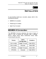
Page 11: ... Converter Install Your Converter MDI MDI X Connection The MDI MDI X function alleviates the worry of type of cable to use to connect the converter with a 10BaseT device Simply follow these instructions below when connecting the converter Device Cable Configuration Selection Hub or switch Straight Through Select MDI X Hub or switch Crossover Select MDI DTE NIC Straight Through Select MDI DTE NIC C...

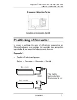
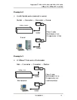
Page 12: ...tch Positioning of Converter In order to achieve the aim of effectively expanding an Ethernet network one solution is to position two converters back to back between the following end devices Example 1 Two LAN Switch workgroups Switch Converter Converter Switch 10Base Switch 100M 100M Fiber Cable Multimode 2 km Singlemode 12 km 10Base Switch ...

Page 13: ...LAN Switch and a network s server Switch Converter Converter Server Example 3 A 10BaseT Hub and a Workstation Hub Converter Converter Station 10Base Switch 100M 100M Fiber Cable Multimode 2 km Singlemode 12 km Server 10Base Hub 100M 100M Fiber Cable Multimode 412 m Singlemode not recommended Workstation ...

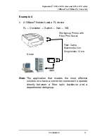
Page 14: ...k and a FL device FL Converter Switch Hub WS Note The application that creates the most effective solution is to have a converter connected to operate directly between a fiber optic backbone and a departmental workgroup 100M Fiber Cable Multimode 2 km Singlemode 12 km Server Workgroup Printer with Fiber Print Server ...

Page 15: ... end of the cable to the RJ 45 jack on the 10BaseT device Converter to Converter or 10BaseFL Device Connection 1 Connect one ST or SC end of a fiber cable to either ST or SC connector on the converter The other end of the cable will connect to the ST or SC connector on the other converter or the10BaseFL devi ce The transmit Tx connector on one 10BaseFL device must connect to the receive Rx connect...

Page 16: ...al LED to enable you to determine the status of the converter and to also see what is happening across your network Their functions are as follows PWR Power Illuminated during normal operation LNK Link Illuminated when receiving link pulses from compliant devices RCV Receive Flashing or illuminated when data packets are being received ...

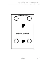
Page 17: ...ncluded in the packaging This converter can also be mounted on a vertical surface Just use the template opposite and mark the position of the holes Simply use two screws and mount the converter in place Please exercise caution when using power tools Also take care to install this unit away from damp or wet locations or in close proximity to very hot surfaces This will have a detrimental effect on ...

Page 18: ...Signamax 065 1140 series and 065 1150 series 10BaseT to 10BaseFL Converter Mounting 13 Bottom of Converter Connector End ...

Page 19: ...ing if a network performs to the maximum throughput 24mm 6mm Try to maintain a bend radius of min 4x the diameter of the cable for UTP and 100x for fiber Try not to allow the cable to twist too much this creates a strain on the internal cables Place cable ties at regular intervals do not over tighten cable ties try to avoid using with fiber Do not stretch the cable especially on corners in vertica...

Page 20: ...N Phone 46 0 293 228 88 Fax 46 0 293 228 89 Phone 49 81 35 9303 0 Http www aesp se E mail info aesp se JOTEC AESP AS NORWAY Telefon 23 14 17 00 Ordrefax 23 14 17 10 Karihaugveien 102 Postboks 50 Ellingsrudasen 1006 Oslo Norway Phone 47 23 14 1700 Fax 47 23 14 1710 Http www jotec no E mail jotec jotec no AESP Russia RUSSIA Kronshtadtsky Blv 125499 Moscow Russia Phone 7 095 456 0704 Phone 7 095 456 ...

Reviews: