background image


25 

SIGNAMAX LLC • www.signamax.eu 


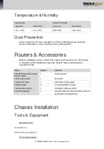
Temperature & Humidity  


Temperature  

Relevant humidity  

Long-term  

Short-term  

Long-term  

Short-term  

15

°

C ~ 30

°

0

°

C ~40

°

40%~65% 

10%~90% 

Dust Prevention  

Dust is harmful for the operation of 065-1530 Signamax Security 
Router. Maintain a clean and dust-free atmosphere.  

Routers & Accessories  

Before installing router, check the router and accessories. Following 
is the 065-1530 Signamax Security Router basic configuration 
equipment list: 
 

Name 

Number 

Remarks 

065-1530 Signamax Security 
Router chassis 

Router chassis 

Power supply cable 

220V/10A 

Console port cable 

RJ45-DB9 crossing cable 

Ethernet cable 

Connected Ethernet cable 

Technical documents 

Installation manual and CD 

Product packaging 

Includes foam anti-shock material, external 
packing box and plastic bag 


Chassis Installation  

Tools & Equipment  


Needed tools:  

 
Screwdriver  
 
Anti-static equipment 

 
Connected cable:  

Summary of Contents for 065-1530

Page 1: ...Signamax Security Router Model 065 1530 Install Guide Revision A1 ...

Page 2: ......

Page 3: ...LIZED E1 E1 SERIES 13 1 port Non channelized E1 1E1 13 1E1 Interface Module Indicator 13 1E1 Interface Connected Cable 13 1E1 Interface Attributes 13 FREQUENCY BAND MODEM M336 SERIES 14 1 port 33 6K Frequency band MODEM 1M336 14 1M336 Interface Dialup DIP 14 1M336 Interface Module Connected Cable 15 1M336 Interface Attributes 15 BASE BAND MODEM M128 SERIES 15 1 port 128K base band MODEM 1M128 15 1...

Page 4: ...e Humidity 25 Dust Prevention 25 ROUTERS ACCESSORIES 25 CHASSIS INSTALLATION 25 Tools Equipment 25 Machine Installation 26 Connecting Power Supply 26 Grounding Connection 27 Main Control Board Cable Connection 27 Console Port Connection 27 Grounding Wire Connection 29 MODULE INSTALLATION 29 Rack Desk 29 Panel Wire Connection 29 Hardware Installation 30 INTERFACE CABLE CONNECTION 30 1SAE Module Cab...

Page 5: ...ses 065 1530 Signamax Security Router series modular router provides a set of high efficiency and low cost network connection solutions 065 1530 Signamax Security Router supports the following applications Computer network interconnection Multi service data integration Branch institute dialup and dialup backup service Internet and enterprise Extranet access Hardware Features 065 1530 Signamax Secu...

Page 6: ...cessful PWR system power supply indicator On After power on SLOT1 slot 1 status indicator ACT voice card module data RDY slot has voice card module link status SLOT 0 slot 0 status indicator ACT insert module data indicator RDY inserting module link status CONSOLE console port TXD sending console port data RXD receiving console port data FETH1 Ethernet interface1 100M 10 100M Ethernet interface da...

Page 7: ...F Power supply switch Right is OFF and left is ON INPUT AC 100 240 1A input SLOT1 Bus slot VOP VOS voice module SLOT0 Interface module decides interface form Fast serial bus slot MIM module SLOT1 voice card module slot for VOP VOS serial module SLOT0 MIM module slot which adopts modular design 065 1530 Signamax Security Router System The following table explains 065 1530 Signamax Security Router b...

Page 8: ...wer supply Confirm before shipment Environment temperature 0 40 C Environment humidity 10 90 Non condensing Power supply rating power 45W Maximum power consumption 15W 065 1530 Signamax Security Router Functionality The following table explains 065 1530 Signamax Security Router functionality and supported protocols and services Protocols services Description Network protocol WAN supports PPP PPP c...

Page 9: ...le with CISCO ODR Dial on demand routing DDR Policy routing Multicast IGMP PIM SM PIM DM DVMRP Hot backup VRRP VBRP compatible with CISCO HSRP Network service ARP Proxy ARP L2TP Configure command level protocol to guarantee unauthenticated user not to intrude into router IP packet filter firewall IP UNNUMBERED IP policy routing DHCP relay PAP CHAP validation EASY IP NAT network concealing RADIUS v...

Page 10: ...debugging information support Support log function Security IP packet filter firewall PAP CHAP MD5 NAT RADIUS TACACS and IPsec data encryption 065 1530 Signamax Security Router Main Board The 065 1530 Signamax Security Router main board comprises three fixed interfaces one voice card slot one MIM slot six indicators and power supply jack and one fixed interface The 065 1530 Signamax Security Route...

Page 11: ...ts SLOT0 and SLOT1 SLOT0 comprises MIM slots which can be inserted into different modules SLOT0 supports the following modules Ethernet interface module Sync async interface module Async interface module E1 CE1 interface module U interface module ST interface module Base band MODEM module Frequency band MODEM module VOP VOS module SLOT1 is voice card slot used for VOP VOS module which can access t...

Page 12: ...uter is a modular router It provides two slots SLOT1 is voice card slot for VOP and VOS serial voice module SLOT0 is an MIM slot compatible with all interface modules of Signamax routers Following are the modules 1SAE 1CE1 1E1 1M336 1M128 1U 1VOP 2VOP 1VOS 2VOS 1ETE 1ST ...

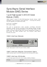
Page 13: ...5 1530 Signamax Security Router sync async serial interface default working mode is sync The sync serial interface is in DTE or DCE mode In DTE mode it receives external DCE clock such as external sync modem In DCE mode the router provides clock The V24 V35 mode switch functions via panel 1SAE Interface Module 1 port high speed V 24 V 35 serial module 1SAE 1SAE Interface Module Connected Cable 1SA...

Page 14: ...d E1 Module 1CE1 The 1 port channelized E1 module provides 1984K multi timeslot data flow receiving and sending and processing port As CE1 interface it divides slot 1 31 to different groups and each group timeslot after using binding as one interface 1CE1 Interface Indicator 1 port channelized E1 1CE1 indicator LOS On Cannot check frame sync signal Off After sync 1CE1 Interface Connected Cable 1CE...

Page 15: ...CE1 It can be divided into 32 timeslots and timeslot 0 of E1 can be used to transmit data in unframed mode to realize 2M transparent transmissions 1E1 Interface Module Indicator 1E1 interface module 1 port non channelized E1 1E1 1 port non channelized E1 1E1 indicator LOS On Transparent 2M transmission On Non transparent and cannot check frame sync signal Off After sync 1E1 Interface Connected Cab...

Page 16: ...DEM 1M336 1 port 33 6 K frequency band MODEM works in sync or async mode 1M336 Interface Dialup DIP 1M336 interface module 1 port 33 6K frequency band MODEM 1M336 DIP 1 port 33 6K frequency band MODEM 1M336 DIP Mode DIP switch configuration Description 1 2 Frequency band MODEM mode OFF OFF LINE port used as inbuilt frequency band MODEM interface Console port mode ON OFF LINE port used as CONSOLE p...

Page 17: ...uency band MODEM 1M336 attributes Attributes Description Tie in RJ45 Interface number 1 Supported link protocol PPP Frame relay X 25 HDLC Supported network protocol IP Base band MODEM M128 Series 1 port 128K base band MODEM 1M128 1M128 Module Indicator DIP Switch 1M128 interface module 1 port 128K base band MODEM 1M128 The 1 port 128K base band MODEM 1M128 indicator ACT On Link established ...

Page 18: ...Reservation 1M128 Module Connected Cable 1M128 module connected cable is RJ45 4 5 signal cable or RJ11 line 1M128 Interface Attributes 1M128 interface attributes 1 port 128K base band MODEM 1M128 interface Attributes Description Tie in RJ45 Interface number 1 Supported link protocol PPP Frame relay X 25 HDLC Supported network protocol IP ISDN U Series 1 port ISDN U Module 1U 1 port ISDN U module c...

Page 19: ... Light on When using channel B2 and the rate is 128K 1 port ISDN U module 1U DIP switch Mode DIP switch configuration Description 1 2 Loopback ON Reservation 1U Module Connected Cable 1U module connected cable RJ45 4 5 signal cable or RJ11 line 1U Interface Attributes 1 port ISDN U module 1U interface attributes Attributes Description Tie in RJ45 Interface number 1 Supported link protocol PPP Supp...

Page 20: ...t IP phone module 1VOP indicator V1 IP phone module indicator and the light is on during the call V2 1VOP module may not have this light and if it has the light will be not on 1VOP Module Connected Cable 1VOP module connected cable is RJ45 4 5 signal cable and RJ11 line 1VOP Interface Attributes 1 port IP phone module 1VOP interface attributes Attributes Description Interface RJ45 jack Interface n...

Page 21: ...one module 2VOP indicator V1 IP phone module indicator Light on After pickup during the call V2 IP phone module indicator Light on After pickup during the call 2VOP Module Connected Cable 2VOP module connected cable is RJ45 external cable 2VOP Module Interface Attributes 2 port IP phone module 2VOP interface attributes Attributes Description Interface RJ45 jack two RJ11 plugs Interface number 2 RJ...

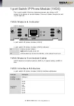
Page 22: ...OS 1 port switch IP phone module 1VOS indicator V1 IP phone module indicator Light on During the phone call V2 1VOS module may not have this indicator or the lamp will never be on 1VOS Module Connected Cable 1VOS module connected cable is RJ45 4 5 signal cable and RJ11 line 1VOS Interface Attributes 1 port switch IP phone module 1VOS interface attributes Attributes Description Interface RJ45 jack ...

Page 23: ...hone module 2VOS 2 port switch IP phone module 2VOS indicator V1 IP phone module indicator Lamp on During the phone call V2 IP phone module indicator Lamp on During the phone call 2VOS Module Connected Cable 2VOS module connected is RJ45 2VOS Module Interface Attributes 2 port switch IP phone module 2VOS interface attributes Attributes Description Interface RJ45 jack Interface number 2 RJ11 Suppor...

Page 24: ...1ETE indicator LINK On Link connected Tx Data sending lamp shining Data sending Rx Data receiving lamp shining Data receiving 1ETE Module Connected Cable RJ45 twisted pair 1ETE Module Interface Attributes 1 port Ethernet port 1ETE attributes Attributes Description Tie in RJ45 Tie in number 1 Supported protocol 802 3 ISDN S T Module ST Series 1 port ISDN S T Module 1ST 1 port ISDN S T module provid...

Page 25: ...nel indicator On Using channel B1 with a rate of B1 64K or B1 B2 128K B2 B2 channel indicator On Using channel B2 with a rate of B2 64K or B1 B2 128K 1ST Module Connected Cable 1ST cable is RJ45 connected Ethernet cable 1ST Module Interface Attributes 1 port ISDN S T module 1ST interface attributes Attributes Description Plug RJ45 Plug number 1 Supported protocol PPP ...

Page 26: ... stable functioning of routers maintain stable temperature and humidity in the equipment room Environment temperature 0 40 C Humidity 10 90 Non condensing 065 1530 Signamax Security Router configures its fan and the theory of radiation is take out the cold air from the left and radiate the hot air out from right via the fan Around the radiation hole the space should be no less than 10cm We suggest...

Page 27: ...outer and accessories Following is the 065 1530 Signamax Security Router basic configuration equipment list Name Number Remarks 065 1530 Signamax Security Router chassis 1 Router chassis Power supply cable 1 220V 10A Console port cable 1 RJ45 DB9 crossing cable Ethernet cable 2 Connected Ethernet cable Technical documents 1 Installation manual and CD Product packaging 1 Includes foam anti shock ma...

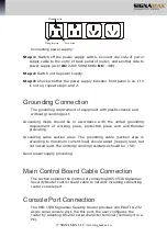
Page 28: ... x 44mm W D H Following is the installation process Step 1 Fix angle iron on the front panel or back panel sides with bolts Step 2 Place router on empty slot Step 3 Fix the angle iron to slots with bolts Step 4 Fix the bracket and fixed angle iron over the rack Connecting Power Supply 065 1530 Signamax Security Router adopts stable power supply switch system and it has lower requirement of AC AC p...

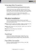
Page 29: ... in accordance with the united grounding requirement of working place protection place and anti thunder grounding Grounding cable section area The grounding cable section area is according to maximum current load should adopt copper lead but not naked lead The united grounding resistance should be 5Ω Good power supply grounding Main Control Board Cable Connection The section explains the method of...

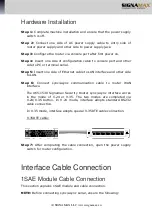
Page 30: ...w signamax eu Step 1 Find a character terminal It can be standard terminal with RS 232 serial or normal PC Step 2 Ensure that power supply is off for router or terminal Connect RS 232 serial and console port with cables ...

Page 31: ...allation 065 1530 Signamax Security Router adopts modular system structure and different kinds of interface configuration Following are the module installation steps Step 1 Choose the module and interface relation of module and slot refers to basic configuration and module configuration list Step 2 Insert module into slot Insert the module circuit board into interface card slot Step 3 Push in the ...

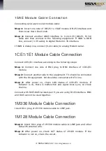
Page 32: ...able to LAN interface and other side to LAN Step 6 Connect sync async communication cable to router WAN interface The 065 1530 Signamax Security Router sync async interface works in the mode of V 24 or V 35 The two modes are completed via V 24 V 35 button In V 24 mode interface adopts standard RS232 cable connection In V 35 mode interface adopts special V 35DTE cable connection V 35DTE cable Step ...

Page 33: ...ole type MODEM Multiplexer CSU DSU Rate and transmission distance Sync async serial supports different signal standards and baud rate in different working modes Choose cables according to prevailing actual conditions Signal maximum transmission distance and BR should be relevant to cables V 24 cable rate and transmission distance BR bps Max transmission distance m 2400 60 4800 60 9600 30 19200 30 ...

Page 34: ...p 1 Connect one side of BNC plug to BNC interface of 1CE1 E1 module Step 2 Connect another side to the equipment TX should be connected with the RX equipment RX should be connected with TX line Step 3 After power on check LOS status of 1CE1 E1 module If indicator is on there is malfunction and signal loses sync so check the line Connect with RJ45 RJ45 twisted pair if you are using RJ45 interface B...

Page 35: ...call pay attention to the indicator of 1VOP 2VOP card back panel The indicator and Active light should be on 1VOS 2VOS Module Cable Connection Connecting VOS module cable Step 1 Insert telephone line to RJ11 RJ45 interface of 1VOS 2VOS and another side to small switch or external junction box Step 2 When having the phone call pay attention to the indicator of 1VOS 2VOS card back panel The indicato...

Page 36: ...34 SIGNAMAX LLC www signamax eu Connecting 1ST module cable Step 1 Insert RJ45 plug of 1ST module cable to RJ45 jack Step 2 Connect another side of RJ45 plug to related equipment wire ...

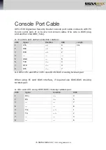
Page 37: ...nterface which can be connected to HUB RJ45 direct connected cable type 5 twisted pair connection relation RJ45 Signal Direction RJ45 Description Length 1 TX 1 Twisted pair 1 2m 2 TX 2 3 RX 3 Twisted pair 2 6 RX 6 4 4 Twisted pair 3 5 5 7 7 Twisted pair 4 8 8 RJ45 crossing connected cable type 5 twisted pair connection relation RJ45 Signal Direction RJ45 Description Length 1 TX 3 Twisted pair 1 2m...

Page 38: ...B9 hole A 3 console port cable connection relation RJ45 Signal Direction DB9 Length 1 CTS 8 3m 2 DSR 6 3 RXD 2 4 5 GND 5 6 TXD 3 7 DTR 4 8 RTS 7 A 3 RM2 1E1 and RM2 1CE1 uses RJ45 RJ45 crossing twisted pair When using E1 card RJ45 interface if required use RJ45 RJ45 crossing twisted pair A 4 E1 and CE1 using RJ45 RJ45 crossing twisted pair RJ45 Signal Direction RJ45 1 RX 4 2 RX 5 3 7 6 8 4 TX 1 5 ...

Reviews: