background image

31 

Using 
CTLWIN  

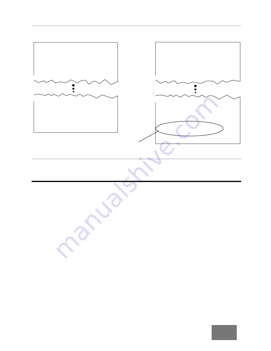
Example 3:  Adding Components Not Learned 


                Original Test Program


Edited Test Program


*695BAE-MULTI

(695BAE-MULTI

 J1  ACEFA1
 J2  1A59C0

WIRE LIST SIGNATURE:69D075-A58M0
INSUL TEST PARM SIGNATURE:2J6NH

HIPOT SOAK TIME  0 SEC

1   J1-001  J2-001
2   J1-004  J2-002

CHECK COMPONENTS
1 DIODE J1-007 J2-008

)


Help for CTLWIN 

You can get more information about CTLWIN by clicking 

“help” while in the program.  You can 

access context sensitive help by highlighting a field or menu item and pressing F1.   

*695BAE-MULTI

(695BAE-MULTI

 J1  ACEFA1
 J2  1A59C0

WIRE LIST SIGNATURE:69D075-A58M0
INSUL TEST PARM SIGNATURE:2J6NH

HIPOT SOAK TIME  0 SEC

1   J1-001  J2-001
2   J1-004  J2-002

CHECK COMPONENTS
1 DIODE J1-007 J2-008
2 CAP J1-006 J1-003 50 nF 10 %
3 DIODE J1-008 J2-009 LED

)


Capacitor and LED 
diode components 
added. 

Summary of Contents for 1100H+

Page 1: ...derutilized and idle equipment along with credit for buybacks and trade ins Custom engineering so your equipment works exactly as you specify Critical and expedited services Leasing Rentals Demos In stock Ready to ship TAR certified secure asset solutions Expert team I Trust guarantee I 100 satisfaction All trademarks brand names and brands appearing herein are the property of their respective own...

Page 2: ...Version 2012 1 0 March 27 2012 1100H User s Manual ...

Page 3: ...Signature 1100H User s Manual Version 2012 1 0 March 27 2012 Copyright by Cirris System Corporation 1991 Parkway Boulevard Salt Lake City Utah 84119 2026 United States of America All Rights Reserved ...

Page 4: ...ter Signatures 17 The Loaded Test Program and Tester Memory 17 Using the Tester 18 Creating a Test Program 18 Learning a Cable With No Connections 19 Documenting a Test Program 20 Testing a Cable 21 Test Summaries 23 Using the Probe 23 USB Thumb Drive 24 Creating Folders 25 Managing Test Programs 26 Using CTLWIN 29 Common Uses for CTLWIN 29 Running the CTLWIN Software 29 Editing Test Programs 30 H...

Page 5: ... Resistance 47 Component Resistance 48 High Voltage Settings 49 Hipot Test 49 High Voltage 50 HV Insulation Resistance 51 Duration 52 Hipot To 53 High Capacitance Shield 53 Max Soak 54 Soak Until Good 55 Soak for 55 Hipot Mode 55 Frequency 57 DWV Voltage 57 DWV Max Current 57 HV Insulation Voltage 58 Insulation Resistance Time 58 Component Setting Test 59 Learn Components 59 Components Learned and...

Page 6: ...er Configuration 79 1100 Upgrade Application 79 1100 Utilities Application 80 1100 File Compression Utility 82 SPC Data Collection 84 Checking Version Information 86 General Information 87 Calibration 87 Maintaining Adapters and Fixturing 87 Service 87 Conditions for Operation 87 Appendix 84 Specifications 84 Warranty 86 ...

Page 7: ...stomer Support If you need assistance with your 1100H tester a customer support representative is ready to assist you In the USA call Cirris customer service toll free at 1 800 441 9910 Outside the USA enter the URL www cirris com contact html to find the Cirris Sales Office nearest you You Should Have Received Setup 1100H Tester Power Supply Quick Reference Guide Users Manual Power Cord Plug type...

Page 8: ...on allows you to store specific test information and retrieve that information for analysis To enable the SPC Data Collection option see 1100 Utilities Application on page 80 For more information see SPC Data Collection on page 84 Scripting This option allows you to adapt the tester s behavior to fit your needs add new features and ease automation of tasks in the tester Scripting can also be used ...

Page 9: ... Hipot Safety Set Auto Hipot to OFF When this option is set to OFF see page 41 the analyzer does not automatically Hipot test Instead the analyzer s display prompts Ready To Hipot after testing for continuity and resistance This requires the operator to manually press the Function switch or Hipot button to conduct a Hipot test Having manual control of the Hipot test should give the operator ample ...

Page 10: ...urn on the tester and make sure the main menu displays Note If connecting either a printer or Scanner Add ons see the applicable sections that follow otherwise skip to Tester Basics on page 9 Probe Well grounded power is essential for the tester to operate accurately Power Supply Power Cord Although not required a thumb drive allows extra storage capacity and test program mobility A thumb drive is...

Page 11: ...nd to the printer Caution The 1100H is NOT compatible with serial printers If you plug a serial printer into the serial port you may damage the tester What printer will work 1100 testers require a parellel printer with an Epson Centronics style parallel port Printers that require Windows drivers will not work You will need a printer that is DOS compatible and capable of receiving ASCII text You ca...

Page 12: ...the removable J1 J2 cover plate to the horizontal position Note The only time to remove the J1 J2 cover plate is when attaching an Add On Scanner 2 Turn the fasteners on the removable J3 J4 cover plate to the horizontal position 3 Remove both cover plates from the tester 4 Carefully remove the scanner assembly turn it upside down and put it next to the tester Horizontal Position J1 J2 Cover Plate ...

Page 13: ...ewdriver or hard flat object 6 Carefully place the scanner assembly back into the tester Make sure the Add On connector sticks out to the side of the tester 7 Mate the Add On connectors make sure they are fully connected 8 Push the connectors into the main unit Cover Piece Add On Connector Scanner Assembly Scanner Add On Plastic Rivet ...

Page 14: ... 10 Re attach the cover plates 11 Label the adapter positions on each additional cover plate with a permanent marker as shown Note Labeling the coverplates identifies adapter positions to help you understand tester prompts and error messages Side Latch Continue this sequence on subsequent Add Ons Label the first Add On coverplate J6 J8 J5 J7 Label the second Add On coverplate J10 J12 J9 J11 ...

Page 15: ...his symbol indicates that the selection cannot be changed By connecting a computer to the tester you can choose to lock or to unlock certain menu selections You may want to use this capability may be used if for example you wanted to keep operators from creating new test programs or changing tester settings For more information see 1100 Utilities Application on page 80 Tester Basics Menu Title Alw...

Page 16: ... 5 Press Accept to save the new volume setting 6 Press back to return to the main menu The speaker selections are OFF LOW MEDIUM and HIGH As you adjust the speaker volume you will hear audible beeps indicating the change in volume SIGNATURE 1100H Set Preferences Set Up Test Program TEST 1B4137 4Z020 SET USER PREFS Set Test Methods Set Hipot Methods Set Test Count SET VOLUME HIGH ACCEPT CANCEL SET ...

Page 17: ...3 J4 cover plate sideways 2 Remove the cover plate from the tester 3 Slide in the adapter against the edge of the scanner until it fully seats being careful not to bend the pins Note Adapters should be added with the J1 J2 cover plate in place turn sideways Cover plate ...

Page 18: ...ons and then the J3 J4 positions 4 Reattach the cover plate and turn both fasteners to the vertical position to lock it in place Caution Always use the cover plates Without the coverplates attached the interfacing connectors on the 1100H may become damaged rotate vertically J1 J2 J3 J4 ...

Page 19: ...re used for connectors with up to 64 points Quad High Adapters are used for connectors with up to 120 points High Voltage Adapters Special High Voltage Adapters are required to do hipot testing above 1000 VDC or above 707 VAC Note For more information on which adapters are available with an HV option visit www cirris com or call 1 800 441 9910 Standard part numbers start with an A High voltage par...

Page 20: ... labels on the cover plates Which positions are these three adapters in The Single High Adapters are in positions J1 and J2 The Double High Adapter is in position J3 J1 Label J2 Label J3 Label J4 Label The J1 label shows how a Single Double or Quad High Adapter occupies the J1 position Single High Adapter in J1 Double High Adapter in J1 Quad High Adapter in J1 ...

Page 21: ... If you saved the test program the original positions will be displayed in the tester see Adapter Signatures on page 17 or on the documentation used for the test Pins Nets and Net Lists The word pin is generically used in this manual and in the tester interface to describe an individual contact or terminal in a connector An interconnection between two or more pins in a cable is called a net When t...

Page 22: ...he position where adapters are installed The Last Part of the Cable Signature The last five digits of the Cable Signature are called the Parameter Signature which identifies Test Parameter Settings for the test Some examples The Cable Signature for each of these cables indicates they have identical connections but different Test Parameter Settings These two cables are tested with the same Test Par...

Page 23: ...Internal Memory The C drive is the tester s internal memory and default drive In addition to the last loaded test program the C drive contains up to 99 memory locations that can store test programs For example this screen shows test programs stored in memory locations 4 5 and 6 External memory A thumb drive is external memory which expands storage capacity For more information see USB Thumb Drive ...

Page 24: ...e following a Make sure the new Cable Signature or file name matches the previously verified test If this is the first time creating the test a Press Verify Test b Scroll down c Verify that the learned connections match the build list of the cable exactly d Double check the Test Parameter Settings Note If a printer is connected you can verify by printing For more information see Documenting a Test...

Page 25: ...nded cables 1 Install the correct adapters a Remove the J3 J4 cover plate b Install the correct adapters c Replace the cover plate 2 Learn the test setup a From the main menu press Set Up Test Program b Press Create New Test c Press LEARN 3 Verify there are no connections a Press CONTINUE LEARN 4 The test program is ready for use a Save the learned test OR Start testing CABLE LEARNED Verify Test S...

Page 26: ...2 If a printer is connected print the results a Scroll down to view the print option b Press Print If a printer is not connected transcribe the results a Press Verify Test b Scroll down and record the information on an 1100H Cable Documentation Form blank form in appendix CABLE LEARNED Verify Test Save Test TEST 1E670 2L35H CABLE LEARNED Verify Test Save Test TEST 1E670 2L35H CABLE LEARNED Verify ...

Page 27: ... J1 Adapter Signature F5B4E0 J2 Adapter Signature 03FAC1 Connection Resistance Auto 5 Insulation Resistance 50M 3 Attach the cable to be tested and start the test a If you have not done this already press Test for the loaded test program b Attach the first cable to be tested Note If the User Preference Test Mode is set to CONTINUOUS the test will start automatically If Test Mode is set to SINGLE T...

Page 28: ...not perform the intermittent test If the cable passes The green LED will light up The screen will display PASSED ALL TESTS If the Test Mode is set to CONTINUOUS the tester will automatically scan for intermitants and emit a Tick Tick Tick sound Each tick signifies a good low voltage test of the cable If the cable fails The red LED will light up The screen will display the type of error You can pre...

Page 29: ...t results of the batch Note You can change the format of the test summary to display the count for good cables only For more information see Test Count on page 42 To Clear or Reset a Test Summary When finish a run of cables and have the summary data you need press STOP TEST RUN to complete the run The summary counts Total Good and Bad will be reset to 0 in preparation for another run Using the Pro...

Page 30: ...will be truncated The first six characters will display followed by a right arrow and a number For this reason Cirris recommends keeping custom file names to eight characters or less To view custom file names up to 16 characters you can compress your files with Cirris compression utility see 1100 File Compression Utility on page 82 File names MUST be followed by dot WIR for the test program to app...

Page 31: ...een after you select the thumb or network drive letter Press the folder s button to view the files in the folder As with file names folder names longer than eight characters will be truncated in the tester The first six characters will be followed by a right arrow symbol and a number After you select a folder you can press the button next to this symbol to take the screen up one folder level D C n...

Page 32: ... and verifying a sample cable OR after editing a test program Saving the Loaded Test Program 1 From the main menu scroll down 2 Press Manage Files 3 Press Save 4 Select the following b A drive letter c A folder d A memory location Note Selecting a memory location saves the test program in the tester Note Cirris recommends recording the test program information on the 1100H Cable Documentation or 1...

Page 33: ...Delete Files 4 Press Mark Files 5 Press the buttons next to the files you want to delete arrows indicate that a file is marked for delete Use the 1100H Test Program Location Listing or other documentation to verify the correct test program to be deleted 6 Press the back button 7 Press Delete Marked DELETE 0 FILES Mark Files Delete Marked CANCEL C C E Z F SIGNATURE 1100H Manage Files Version Inform...

Page 34: ...the single file as a ccf file FILE CONTENT This option will display all files in the bundle or the single files 4 Press Mark Files 5 Select the D drive and press the buttons next to the bundle or file you want to import right arrows indicate that a file is marked for import Use the 1100H Test Program Location Listing or other documentation to verify the correct test program to be imported 6 Press ...

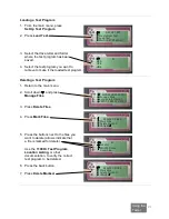
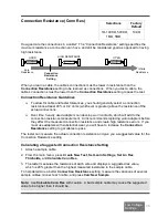
Page 35: ...s and capacitors When learning these components the 1100H measures the value and automatically sets a 10 default tolerance With CTLWIN you can edit the component value and the tolerance Create Links and Component Definitions If the tester senses a component but cannot identify the component as a resistor diode or capacitor the tester creates a link in the test program to ensure no high voltage is ...

Page 36: ...8 J2 009 6 65 K ohm 5 3 CAP J1 006 J1 002 420 nF 10 4 RESIS J1 005 J2 005 1M ohm 10 DT SONAR MODULE 984123 2J8NM J1 D507F1 CONNECTION RESIS 10 0 ohm LV INSULATION RESIS 100k ohm HIPOT VOLTAGE 50 V INSULATION RESIS 5 00M ohm HIPOT DURATION 1 SEC APPLY HIPOT TO ALL ADAPTER PINS HIPOT SOAK TIME 0 SEC 1 J1 001 J1 002 2 J1 003 J1 004 LABELS J1 001 HEADER_PIN1 J1 002 HEADER_PIN2 J1 003 RED_WIRE J1 004 B...

Page 37: ...7 J2 008 Help for CTLWIN You can get more information about CTLWIN by clicking help while in the program You can access context sensitive help by highlighting a field or menu item and pressing F1 695BAE MULTI 695BAE MULTI J1 ACEFA1 J2 1A59C0 WIRE LIST SIGNATURE 69D075 A58M0 INSUL TEST PARM SIGNATURE 2J6NH HIPOT SOAK TIME 0 SEC 1 J1 001 J2 001 2 J1 004 J2 002 CHECK COMPONENTS 1 DIODE J1 007 J2 008 ...

Page 38: ...s how low the resistance of a connection must be before it is recognized as a connection After a successful learn the Learn Settings become the Test Parameter Settings for that cable until it is changed Test Parameter Settings Test Parameter Settings affect how a cable is tested An example of a Test Parameter Setting is the level of high voltage applied to a cable during the high voltage test The ...

Page 39: ...Settings Factory Defaults Connection Resistance 10 0Ω LV Insulation Resistance 100KΩ Component Resistance OFF High Voltage Settings Factory Defaults Hipot Test STANDARD High Volt ge 50 HV Insulation Resistance 5MΩ Duration 01 seconds for VDC and 1 cycle for VAC Hipot To ALL PINS High Capacitance Shield NO Max Soak 0 seconds Restoring Factory Default Preferences and Settings The factory defaults fo...

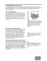
Page 40: ...cause of its complexity the high voltage test is explained in more detail below Note The high voltage test will not occur if the test setting Hipot Voltage is OFF or if the cable fails the low voltage test The intermittent test will not occur if the User Preference Test Mode is set to SINGLE Low Voltage Test The tester checks cables for opens shorts and miswires Components if present are also test...

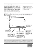
Page 41: ...ielectric Withstand Test The voltage is maintained at the high voltage setting according to a duration setting which can be varied from 0 01 seconds to two minutes During this period the tester performs a Dielectric Withstand Test which checks for high voltage arcs exhibited as sudden current spikes This test determines whether the cable will grossly fail at a given high voltage potential An examp...

Page 42: ... Voltage setting throughout the hipot test However using the Hipot Test Advanced setting allows one voltage to be applied for the Dielectric Withstand Test and another voltage for the Insulation Resistance Test The Voltage Ramps Up As the voltage rises to its High Voltage setting current is limited for safety 0 Voltage Time Current 0 Time Optional High Voltage Soak To help dry out moisture the tes...

Page 43: ...gresses somewhat differently as the graphs below illustrate Using VAC for hipot testing causes current peaks due to cable capacitance These peaks are proportional to how fast the voltage is changing For more information on the differences between DC and AC hipot testing see www cirris com testing guidelines ac_hipot_testing html Voltage 0 Time DWV Voltage Setting in AC RMS IR Insulation Voltage Se...

Page 44: ... Location o Auto Start Set Hipot Methods allows you to access the following user preferences o Auto Hipot o Delay o Hi Speed Hipot o Safety Switch 3 Scroll down to access the following user preferences Auto Print Digital Outputs Volume Date Time Factory Default Each User Preference for the 1100H is described on the following pages User Preferences SIGNATURE 1100H Set Preferences Set Up Test Progra...

Page 45: ...king sound when a cable passes Each tick signifies a successful low voltage scan of the tested cable If there are errors the tester continuously beeps as it scans the cable to help you find the intermittent errors External Switch Selections Factory Default Selectable only if Test Mode is set to SINGLE ON or OFF OFF External Switch allows the tester s digital I O port to receive an input signal fro...

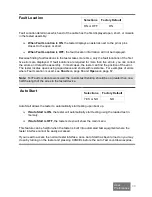
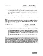
Page 46: ...ates opens using capacitance and shorts with resistance For examples of errors where Fault Location is used see Shorts on page 66 and Opens on page 67 Note For Fault Location to work well the custom test fixturing should be no greater than one half the length of the wires in the tested device Auto Start Selections Factory Default YES or NO NO Auto Start allows the tester to automatically start tes...

Page 47: ...of the hipot test The delay may be set from 1 to 2 seconds Hi Speed Hipot Selections Factory Default ON or OFF ON Hi Speed Hipot determines whether the tester will use advanced algorithms to speed the hipot test When High Speed Hipot is ON the tester uses advanced algorithms The algorithms allow the tester to perform the hipot test much faster by applying high voltage to several nets simultaneousl...

Page 48: ... O connector Safety Switches can be dual palm switches wired in series a foot pedal or a sensor in automated test equipment For more information on wiring a safety switch see Hipot Safety Switch on page 74 Test Count Selections Factory Default GOOD CABLES ONLY or ALL CABLES ALL CABLES Test Count determines the types of tested cable counts listed in the test summary When Test Count is set to ALL CA...

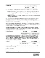
Page 49: ...r company name on the report and choose the data displayed on the report Regardless of the type of report selected you can print a test summary after any test when testing a run of cables Remember when you select a report the same report will be used for all test programs until you change the report selection Digital Outputs Selections Factory Default disable enable pins 5 6 7 8 10 11 pin 7 Cable ...

Page 50: ...ct the appropriate category of Learn Settings 5 Select the specific Learn Setting you want to change You may need to scroll down to see all settings in the category 6 Set the desired value for the Learn Setting Some Learn Settings toggle between two values and others scroll through a range of values 7 Press ACCEPT or back to exit the specific test setting 8 Press back to exit the category of Learn...

Page 51: ...en two values while others scroll to the desired value 7 Press ACCEPT or back to exit the specific Test Setting 8 Press back to exit the category of test settings 9 Press back to exit the Edit menu If you made changes a screen briefly confirms the changes in the loaded test program Note If you edit a loaded test the test is not updated until you save it back to the same memory location Each Learn ...

Page 52: ... affect the measured connection resistance and create high resistance errors If you must use adapters with substantial wear you will have to increase the Connection Resistance setting to get cables to pass The tester can measure the actual connection resistance and give you a suggested value for the Connection Resistance setting Calculating a Suggested Connection Resistance Setting 1 Attach a samp...

Page 53: ...esistance intended connections are considered open as opposed to having high resistance LV Insulation Resistance Guidelines The factory default of 100KΩ should work well for most cable testing applications The higher you raise the LV Insulation Resistance setting the longer it takes for the tester to perform the low voltage test Note Resistances above the LV Insulation Resistance setting will be i...

Page 54: ...e the measurement window between Connection Resistance and Component Resistance settings In this case you potentially have two options Option 1 You can raise the Connection Resistance and Component Resistance settings to test components as connections Option 2 If cable connections have more than 1Ω of resistance lower both the Connection Resistance and Component Resistance settings below the cable...

Page 55: ...nce IR Test The chart below contrasts the settings for the Standard and Advanced Hipot Test Hipot Test Settings Standard vs Advanced Setting Standard Setting Advanced Setting Hipot Mode VDC Allows operator to select either AC or DC for DWV test Frequency N A Allows operator to select the frequency if a VAC is selected for DWV test DWV Current N A Allows operator to select value from 100uA to 1 5mA...

Page 56: ...y be dictated by a customer or engineering specification If you do not have a specification below are some general guidelines The spacing between the pins in a connector as well as the separation of the conductors in a cable limits the amount of voltage that can be applied to a cable Use the manufacturer s specifications for the wire and connectors used in a cable The High Voltage setting affects ...

Page 57: ...ith insulation resistance higher than the Insulation Resistance setting pass the hipot test The HV Insulation Resistance settings are limited by the high voltage settings The table below shows the available Insulation Resistance settings at each of the high voltage settings High Voltage Available HV Insulation Resistance Settings 1000 Volt Unit 5 00MΩ 10 0 MΩ 20 0 MΩ 50 0 MΩ 100 0 MΩ 200 0 MΩ 500 ...

Page 58: ...e the high voltage is applied to each net during the Dielectric Withstand Test which occurs during the hipot test If using an AC test voltage for the Dielectric Withstand Test the duration typically referred to as dwell is set in cycles rather than seconds If you do not have a Duration Specification use the following guidelines Changing Duration Guidelines The default setting for this parameter of...

Page 59: ...leakage occurs from a high capacitance shield to an unused pin High Capacitance Shield High Cap Shield Selections Factory Default YES NO NO High Capacitance Shield allows a cable to pass with one net too capacitive to pass a hipot test This setting is often used when a shielded cable is hipot tested Cable shields usually have substantially higher capacitance because the shield surrounds and has ca...

Page 60: ... change the Advanced Hipot settings and uncheck the box marked Soak Until Good You can then set a Soak For time that applies voltage for the entire time specified before performing the I R test see the next page for more information Max Soak allows the tester to monitor the insulation resistance for a selected period of time If the I R becomes good i e actual I R reading becomes greater than the I...

Page 61: ...pot Test Advanced is selected Selections 002 017 02 1 10 30 60 120 Seconds Soak For applies voltage to each net in the cable for the specified time BEFORE performing the I R test Note Soak For will generally result in a slower hipot test as each net will be soaked for the entire Soak For period Hipot Mode Available only when Hipot Test Advanced is selected Selections May be changed to AC only when...

Page 62: ...gn and testing DOD W 83575A USAF December 1977 states regarding the high potential withstand test This test shall be performed using either a 60 Hz ac test potential or a dc potential Because the wiring capacitance results in higher ac currents that may give erroneous indication of breakdown only the dc test is recommended for cables longer than 3 meters If a VDC is to be used in place of a VAC th...

Page 63: ...the High Voltage guidelines for the settings page 50 are applicable to this setting DWV Max Current Available only when Hipot Test Advanced is selected Selections 100uA 1mA 200uA 0 2mA 500uA 0 5mA 1mA and 1 5mA DWV Max Current determines the maximum current that is allowed to flow out of each net during the Dielectric Withstand Test If current flow exceeds this setting the tester will fail the tes...

Page 64: ...est Note The tester does not permit you to set this voltage higher than the equivalent DWV Voltage This setting specifies a VDC If you do not have a specification for this setting the High Voltage guidelines page 50 are applicable Insulation Resistance Time Insul Res Time Available only when Hipot Test Advanced is selected Selections 002 017 02 1 10 30 60 Seconds Insulation Resistance Time specifi...

Page 65: ...o this Components Learned and Tested The 1100H can learn and test resistors capacitors diodes twisted pairs and 4 wire Kelvin Though twisted pairs and 4 wire Kelvin are not technically components the tester interface uses the term component to describe certain electrical characteristics between points Some components may not be learned but can be effectively tested if the test program is edited Th...

Page 66: ...assign links to resistors with values above 100K and below the Low Voltage Insulation Resistance setting which can be set up to 5M If the tester creates a link for a resistance in the 100K to 1M range the technician can use CTLWIN to replace the link with a resistor command thereby allowing the tester to test the resistance value Links created by the technician In some instances the technician set...

Page 67: ...e feasible For more information see Four Wire Kelvin Testing at http www cirris com testing resistance fourwire html Note 2 wire and 4 wire testing can be put into any combination on the 1100H tester Building 4 Wire Fixturing For the purpose of 4 wire testing the 1100H test points are considered either Type 1 T1 or Type 2 T2 points Each 4 wire pair from the tester must have one of each point The t...

Page 68: ... custom test point labels can be used to remedy the pin out numbering Alternating Method The other way to construct 4 wire fixturing is to use the separate method shown below Although more difficult to construct the separate method will create a Net List which will document correctly without using custom test point Labels A 2 wire Net List can be preserved when converting to 4 wire Note Because th...

Page 69: ...tween the Kelvin points is added to the resistance measurement of the device under test The diagram below shows how the location of the Kelvin points will affect the resistance measurement of the device under test DUT 1 The measurement is only of the device under test This is ideal but in real situations it may be nearly impossible DUT 2 The measurement includes part of the fixture Warning If a lo...

Page 70: ... Test Program 2 Press Create New Test 3 Press LEARN 4 Scroll down and press Probe 4W Point Type Learning a 4 Wire Test Setup Now you can learn a 4 wire test First learn the fixture and then learn the tested device 1 From the main menu press Set Up Test Program 2 Press Create New Test 3 Press Learn 4 Make sure only the 4 wire fixture is connected press Continue to learn the fixture Note Be sure to ...

Page 71: ...ror Tones When the tester finds a cable error it makes error tones based on the type of error Opens single beeps Shorts double beeps Miswires triple beeps High voltage errors triple beeps Error tones give the operator instant feedback if there is a problem For instructions on changing speaker volume see Changing the Speaker Volume on page 10 and Changing Volume and Display Controls on page 86 FAIL...

Page 72: ...ments 2 Shorts that occur between points not used in the net list For example this kind of short would be detailed like this A NET NC SHORT indicates a short exists between two No Connect pins or between a net and a No Connect pin Shorts are caused by Defects in the cable such as frayed wire strains bridging solder joints or conductive contaminates between exposed connections The LV Insulation Res...

Page 73: ... this by sensing the lower capacitance of the unconnected pin Opens are caused by Defects in the cable such as missing or cut wires defective or un inserted connector contacts and cold solder joints Additionally the tester could display an open error when The LV Insulation Resistance setting is lower than the actual resistance of a wire connection The Component Resistance setting is lower than an ...

Page 74: ...oorly crimped wires High resistance in the adapter or tester connector contacts In this case the tester connectors that interface with the adapters may be worn or damaged and need to be replaced A Connection Resistance setting too low for the tested assembly In this case the resistance of a wire or contact is greater than the Connection Resistance setting but less than the LV Insulation Resistance...

Page 75: ...ailed hipot errors occur during the high voltage test Like other error messages press View Print Errors to see the detailed error message For example this message for a hipot failure describes 1 The type of hipot failure AND 2 Which net or test point failed Note The High Voltage error message does not show what the error was to only that it happened from the displayed net For example the error mes...

Page 76: ...ionally the high voltage arc that caused the dielectric failure creates a conductive carbon trail which causes the cable to fail subsequent tests Dielectric Failure This error occurs when high voltage is applied to a cable connection and the tester detects a current spike caused by the discharge of a high voltage arc Dielectric Failures are caused by Exposed cable connections too close to each oth...

Page 77: ...some insulating value by absorbing moisture from the environment The insulating material under test has been incorrectly specified Dielectric Failure On Unknown Point This error occurs when the tester finds a dielectric failure a high voltage arc when hipotting a cable with the High Speed Hipot setting turned ON To locate the error the tester automatically changes out of the High Speed Hipot algor...

Page 78: ... Resistor Missing Capacitor and Missing Diode The tester displays these messages when it does not sense a component where it should be in the cable Possible causes A connection to the component is open The component has not been installed is missing or has a value greater than what the tester can measure Bad Diode The tester displays this message when it senses a defective diode condition Possible...

Page 79: ...he outside of the cabinet Additionally if the cable doesn t pass the test you can use two of the tester s outputs to activate a buzzer and a red light The digital I O port is located on the back of the tester The location and pin out of the connector are as shown The table below shows each of the signals on the digital I O port 91 01 11 21 3 1 5 1 4 1 2 3 4 5 6 7 8 Pin Explanation 1 Input External...

Page 80: ...olts power source on the digital I O connector to supply the DC 5 voltages through the switch circuit as shown below Do not apply an AC voltage to the input P i n 9 D C 5 V o l t s P i n 1 E x t e r n a lS w i t c h I n p u t Hipot Safety Switch The 1100H allows you to start the hipot test by closing an external hipot safety switch The safety switch might be dual palm switches wired in series a fo...

Page 81: ...elow Test Event Name Description Bad Light Off The front panel Bad light is off Bad Light On The front panel Bad light is on Cable Attached The tester sensed a connection between 2 or more test points Cable Counted Bad The tester counted a cable bad in the test summary Cable Counted Good The tester counted a cable good in the test summary Cable Removed The tester sensed the cable is removed Count ...

Page 82: ...o set and HV Test Done P F to reset the output In this example the LED requires only 20 mA so we can use the 5 DC volt supply on the digital I O port to power our circuit Use a resistor in series with the LED to limit the current going through it P in9 D C 5V olts P in10 O utput R esistor LE D How do you choose the resistor The LED in this instance has a forward bias voltage drop of two volts ther...

Page 83: ...each assembly that passes a test In the User Preference Set Digital Output you can select Cable Counted Good to both set and reset the output Remember if the same event is selected for set and reset the tester will sink the output for a 10 millisecond pulse In this case a pulse is all we need to make our stamp mechanism function In this example the solenoid for the air piston requires DC 24 volts ...

Page 84: ... set 5 Scroll up or down to the test event needed to start the operation of the output device press Accept 6 Press R reset 7 Scroll up or down to the event needed to stop the operation of the output device press Accept 8 Press back to return from the Digital Output selection menu The S event sets or sinks the output pin to ground thereby allowing current to flow through the output circuit The R ev...

Page 85: ... serial adapter A serial cable is provided with the CTLWIN kit you received with the tester To download the upgrade file from the Cirris FTP site 1 Type the URL ftp ftp cirris com 1100 in your web browser 2 Double click on the file 1100_verx xx exe where the x xx is the current revision 3 In the File Download dialogue box that comes up click Run to install the 1100 Upgrade software or click Save i...

Page 86: ...ize this feature the tester must have version 4 5a software or higher installed To download and install the 1100 Utilities software 1 Type the URL ftp ftp cirris com 1100 in your web browser 2 Double click on the file 1100_utilities1 0 exe 3 In the File Download dialogue box click Run to install 1100 Utilities or click Save if you will be installing the software on other stations The software inst...

Page 87: ...ick Save To Tester If you want to review the settings that have been saved to the tester click Load From Tester If would like to duplicate the security settings later click Save To File to save the setting information on the computer you are using Click Load From File to access previously saved security settings The Option Manager tab When you click the Option Manager tab you can see the tester se...

Page 88: ...8 characters will be truncated in the tester Compressing the Wirelists 1 Select Windows Start All Programs Cirris System Corporation 1100 Utilities and double click on FileCompression1100 exe 2 When the 1100 File Compression Utility opens select your desired Compression Mode All files compressed and bundled into a single ccb file allows you to import multiple compressed files at one time Each file...

Page 89: ...e into your PC and browse to the thumb drive location 6 If you selected all files compressed and bundled into a single file give the bundle of files a name a file name with the maximum of 8 characters and click Save If you selected each file compressed into it s own file the file name will be auto generated Click Save 7 Transfer the thumb drive from your PC to the tester and power on the tester 8 ...

Page 90: ...er group if stored in Scripting Custom per Cable if stored in Scripting These data elements are stored if Values is turned ON Net or Instruction Label Net or Instruction Measurement These data elements are stored if Error Text is turned ON Error Number Error Code Error Type Error Text Additional data elements may be stored using Scripting in conjunction with SPC Data Collection To use SPC Data Col...

Page 91: ...older The file will be given a name consisting of the tester s serial number followed by C_D i e If your tester serial number is 463658 the file name in the spc_data folder will be 00463658 C_D Note Subsequent runs of SPC Data will not overwrite previously stored information Newer SPC Data will be appended to the end of the existing data file Retrieving and Analyzing SPC Data Use SPC Link or SPC M...

Page 92: ...mbly as shown 3 Using a small screwdriver adjust the speaker or display control Each control is labeled on the PC board These adjustments need to be made with the tester turned on to observe the results If adjusting the speaker access the speaker volume control on the display menu see Changing the Speaker Volume on page 10 Checking Version Information You may check the 1100H software version hardw...

Page 93: ...ts to determine maintenance intervals for testing and or replacing fixturing contacts A good way to check fixture contact resistance is to construct and use a shorting block For more information on creating shorting blocks see http www cirris com adapters test adapt html Service All Cirris Testers are designed as modules for easy servicing Should your Cirris tester require service as directed by C...

Page 94: ...1 2 0 25A to 10 7mA above 10 Dielectric Withstand Current 1mA 2mA 5mA and 1 5A High Voltage Duration or Dwell 10 ms to 120 seconds AC Option 1 7200 cycles High voltage energy limit 35 mJoules Test rate typical Low voltage test 128 test points in 25 seconds High voltage test 01 120 seconds duration per net High speed hipot User selectable Maximum Test Points per net 128 Maximum capacitance per net ...

Page 95: ...with pairs must have a minimum of 3 wires Digital I O Port 4 inputs 0 24 VDC 6 User programmable outputs Sink 24 VDC 500mA max Source Voltages 5VDC 100mA 10VDC 100mA Parallel Port Standard Epson Centronics type parallel interface Memory Nonvolatile storage of up to 99 test programs Power 100 250 VAC 47 63 Hz maximum 50 Watts Dimensions and weight Main unit 14 25 wide x 6 75 deep x 5 25 high 36 2cm...

Page 96: ...ms Corporation is not responsible for special incidental or consequential damages resulting from any breach of warranty or under any other legal theory including lost profits downtime goodwill damage to or replacement of equipment and property and any costs of recovering materials used with the Signature 1100H Cable Analyzer ANY IMPLIED WARRANTIES ARISING OUT OF SALES OF THE SIGNATURE 1100H CABLE ...

Page 97: ...29 J6 J14 J22 J30 J7 J15 J23 J31 J8 J16 J24 J32 Test Parameter Settings Connection Resistance Threshold ______________ Component Resistance Threshold ______________ LV Insulation Resistance Threshold ______________ High Voltage ___________ HV Insulation Resistance Threshold _______________ Duration ____________ Apply Hipot To All Adapter Pins Connections Only Max Soak __________ High Capacitance S...

Page 98: ...Connections continued Net Test Points Components Notes ...

Page 99: ...1100H Test Program Location Listing Unit Serial Number ______________________ Drive Folder Mem Loc Part Number Cable Description Cable Signature File Name ...

Page 100: ...9 Compressed files wirelists scripts 28 Conditions for Operation 87 Connection Signature 16 Continuous Test Mode 39 Contrast See Display adjustment CTLWIN examples 30 installing 29 Customer Support 1 D Default Point Labels 29 Dielectric failure errors 70 Dielectric withstand test 36 Digital I O 73 Display adjustment 86 Documenting Cable Documentation Form 87 88 Memory Location Listing 89 Download ...

Page 101: ...ce 48 Duration 52 High Voltage 50 57 Hipot To 53 HV Insulation Resistance 51 learn 32 Learn Component 59 LV Insulation Resistance 47 restoring factory defaults 33 Test Parameter 32 Learn Component Setting 59 LEDs See Components testing Links 29 30 60 Low voltage errors 66 68 LV Insulation Resistance Setting 47 M Max Soak Setting 35 Memory deleting 27 external 17 internal 17 loading 27 saving 26 Mi...

Page 102: ...eter Settings 32 Test Parameter Signature 16 Test Program Location Listing 26 27 28 89 Test programs creating 18 editing with CTLWIN 29 31 Test summary 23 Test Summary Count 42 Testing 21 34 37 Thumb drive 17 Twisted paired wires See Components testing U Upgrade Appication 79 User aborted hipot error 71 User Preferences 32 Auto Start Test 40 Automatic Hipot 41 External Switch 39 Fault Location 40 ...

Page 103: ...Cable Harness testing made easy ...

Page 104: ...quipment Have surplus equipment taking up shelf space We ll give it a new home Learn more Visit us at artisantg com for more info on price quotes drivers technical specifications manuals and documentation Artisan Scientific Corporation dba Artisan Technology Group is not an affiliate representative or authorized distributor for any manufacturer listed herein We re here to make your life easier How...

Reviews: