60
Component
Settings & Test
Links
In some cases, the tester may sense the electrical characteristics of a component, but
cannot determine if the component is a resistor, diode, or capacitor. When this occurs, the
tester creates a “link” in the test program to ensure that no high voltage is applied across the
component during the hipot test. Essentially, the tester applies high voltage simultaneously
to linked test points; thereby, ensuring voltage is not dropped across the link and that the link
is effectively isolated from other cable connections. During the Low Voltage test, the tester
assures the linked points have a higher resistance than the
Component Resistance
setting.
Links may be created either automatically by the tester or by the technician setting up the
test.
Links created automatically by the tester
When verifying a learned test program, a technician may recognize the tester created links in
the test program’s net list. In some cases, the tester may have assigned a component a link,
because it was outside the tester learn range. However, in some instances, the component
can still be effectively tested if the technician uses CTLWIN to edit the links assigned by the
tester. For example, in order to speed the learn process for the majority of cables, the tester
does not learn component resistances higher than 100K
However, the tester
does
assign
links to resistors with values above 100K
and below the Low Voltage Insulation Resistance
setting, which can be set up to 5M
. If the tester creates a link for a resistance in the
100K
to 1M
range, the technician can use CTLWIN to replace the link with a resistor
command; thereby, allowing the tester to test the resistance value.
Links created by the technician
In some instances, the technician setting up the test program may need to use CTLWIN to
create links in the test program. By linking two or more test points, the tester will treat the
linked points as one net during the hipot test.
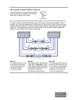
For example,
a cable might have three shields.
During high voltage testing, each shield could have
substantial capacitance between itself and all the
wires it encompasses. To avoid an unsafe shock
hazard during a hipot test, the tester will
not
continue
to charge a highly capacitive net. Turning ON the
setting HIGH CAP SHEILD will ignore the hipot
failure on one of the shields; however, the other two
shields would continue to fail the high voltage test.
To avoid this problem, use CTLWIN to create two
links so the tester treats the shields as one net.
During the high voltage test, high voltage will be
applied simultaneously to all three shields ensuring
their isolation from other cable connections. During
the low voltage test, the tester checks that the
resistance between the linked shields is higher than
the Component Resistance setting.
Capacitance from
shield to each wire
Connections
to Shield 1
Connections
to Shield 2
Connections
to Shield 3
Link
Link

