4
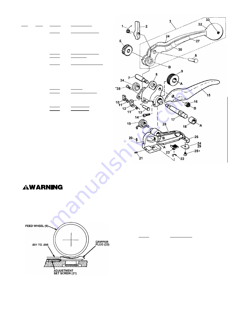
ST-D TENSIONER PARTS LIST
KEY
QTY.
PART #
DESCRIPTION
1
1
003489
Handle pawl spring
2
1
003492
Handle pawl
3
1
003493
Handle
5
1
003488
Ratchet gear
6
1
003494
Handle pawl pin
7
1
023964
Feedwheel support pin
8
1
003490
Feedwheel support
9
1
023954
Feedwheel
10
1
003485
Short retaining pawl
11
2
003483
Retaining pawl spring
12
1
003484
Long retaining pawl
13
1
003486
Retaining pawl pin
14
1
004502
SHCS, #10-32 x ¾
15
1
023953
Reaction handle
16
1
003868
Flexloc thin nut,
d
-24
17
1
003487
Feedwheel shaft
18
1
003478
Bearing
19
1
003479
Feedwheel spring
20
1
023957
Set screw, #10-32 x
e
(Flat point)
21
1
023965
Set screw, #10-32 x
e
22
1
020711
Truarc, #5101-37
23
1
023912
Gripper plug
24
1
023966
Cutter blade
25*
1
023967
FHSS, #10-32 x 5/16
26
1
023952
Base
27
1
183024
Nameplate
28
1
182997
Caution plate
29
1
098228
Protective cover
30
1
003133
Caution plate
31
1
003493
Handle
32
1
306927
Knob
33
1
010057
Roll pin, ¼D x 1-¾LG
34
1
424250
Bushing
35
1
424251
BHCS, 1/4-28 x 1/4
--
1
023963
Brush
When ordering parts, please show tool model, part number,
and description. All recommended spare parts are underlined
and should be stocked.
* Apply one drop of Loctite #271 (Red) or equivalent, available as Signode Part No. 422796.
NOTE: Keys numbers 8, 34 and 35 can be ordered together as Gear Housing Kit, Signode part No. 424436.
All parts must be periodically inspected and replaced if worn or broken. Failure to do this can affect a
product's operation and can result in personal injury.
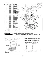
CLUTCH PLUG ADJUSTMENT
1.
Maintain a clearance of .001 to .005 between the feed
wheel (9) and the gripper plug (23) by adjusting the set
screw (21) as needed. See page 9 for the set screw
location on the tool.
2.
Depress the handle (3) to raise the feed wheel support
assembly (8).
3.
While the support assembly is raised, turn in the set
screw (21) clockwise, until it bottoms out.
4.
Back out the set screw (21) 1 3/4 turns for a general
factory setting. If needed, continue to back out or turn in
the set screw according to the following chart of strap
variations. General factory setting is 1 3/4 turns.
STRAP
NO. OF TURNS
502, 504
1 1/2
506
1 3/4
508
2 1/2
1816
1 3/4
1822
2 1/2
814
1 1/2
816, 818
1 3/4
NOTE: As the tool wears, it may be necessary to turn the set
screw (21) in 1/4 to 1/2 turn. This will become apparent if strap
begins to slip in the tool while under tension.


