background image

EU Declaration of Conformity

The Supply of Machinery (Safety) Regulations

1992 (S.I. 1992/3073)

It is hereby declared that the undermentioned machinery has been designed and
constructed to comply with the health and safety requirements defined in EC Directives
2006/42/EC, 2006/95/EC and 2004/108/EC.

Machine Supplier:

Signode
3700 West Lake Avenue
Glenview, IL 60026 U.S.A.

Place of Declaration:

U.S.A.

Declaration Date:

1 March, 2013

Machine Description:

Grippack

Machine Type:

Battery Powered Hand Tool

Provisions with which machinery complies:

2006/42/EC
2006/95/EC
2004/108/EC

Harmonized EuroNorms with which machinery complies:

EN 60734-1:2009
EN 60745-2-18:2009
EN ISO 12100:2010
EN 60204-1:2006
EN 13849-1

Technical Standards with which machine complies:

NA

EC Authorized Representatives:


Tim Dunlavy

G. S. Leine

Manufacturing Manager

Product Support Manager

Signode

Signode Europe

3700 West Lake Avenue

Westring 13, 40721

Glenview, IL 60026 U.S.A.

Hilden Germany

Phone 800-323-2464

Phone 49-2103-96067-0


27

Summary of Contents for GRIPPACK

Page 1: ...SIGNODE 3700 WEST LAKE AVENUE GLENVIEW ILLINOIS 60026 GRIPPACK BATTERY POWERED TENSIONER NOTE Fully charge battery before first use of tool ...

Page 2: ...ing strap or tool When tensioning or sealing position yourself to one side of the strap and keep all bystanders away Using strap not recommended for this sealer can result in strap breakage during sealing Use the correct Signode products for your application 2 TOOL CARE Take good care of the tool Inspect and clean it daily lubricate it weekly and adjust when necessary Replace any worn or broken pa...

Page 3: ...ttery from tool when not in use or before servicing To avoid unintentional starting never carry plugged in tool with finger on switch 11 MAINTAIN TOOL WITH CARE Check Damaged Parts Check for alignment of moving parts binding of moving parts breakage of parts mounting and any other condition that may affect its operation A guard or other part that is damaged should be properly repaired or replaced ...

Page 4: ...ion ENVIRONMENTAL PROTECTION Charger and batteries should be sorted for environmental friendly recycling Do not open the battery Do not throw the used battery into household waste fire or water DISPOSAL This tool is manufactured without any physical or chemical substances which could be dangerous to health The legal prescriptions for disposal of all the parts must be observed The electrical assemb...

Page 5: ...ng Guides 19 Tool Maintenance 22 Maintenance Procedures 23 GRIPPACK Tensioner Tool Battery 120 Volt Charger Part No 800466 Tool Battery 220 Volt Charger Part No 800467 STRAP SPECIFICATIONS STRAP TYPE WIDTH THICKNESS TENSION SEALS Apex Magnus 3 4 19mm to 1 1 4 31 75mm 020 0 5mm to 031 0 78mm 800 to 1500 lbs 3558 6672N 34HOC 114P Note Clean the tool daily with a brush and apply light oil to all the ...

Page 6: ...MAJOR TOOL COMPONENTS 6 TENSIONER FOOT FEEDWHEEL LEVER R__OLLER ...

Page 7: ...he purpose of the green light is to indicate that the battery pack is fast charging It does not indicate the exact point of charge The light will stop blinking in less time if the battery pack was not completely charged When you begin the charging process of the battery pack a steady red light could also mean the battery pack is too hot or too cold Fast charging is only possible when the temperatu...

Page 8: ...ug the charger unless you re charging another battery pack and install the battery pack back into the tool INSTALLING A BATTERY 1 Hold the tool firmly with one hand 2 Using your other hand insert the battery into the tool with a sliding motion 3 Firmly push the battery until fully seated When fully seated the battery locks in place 4 To remove the battery press the Red release button on the batter...

Page 9: ...peration Button Automatic mode b 2 flashes on the Operation Button Manual mode Note When entered into MODE selection the Operation Button will flash the current mode 3 Press the Operation Button to toggle between Automatic and Manual modes Figure 2 4 When correct mode is selected turn Tension Control Knob clockwise to the appropriate tension level 1 through 5 Note When exiting MODE selection the O...

Page 10: ...injury If you have any questions contact your local Signode Representative Strap tension is controlled by setting the control on the rear of the tool Adjust the tool to give the desired tension level Rotate the tension control clockwise to increase strap tension Once the tool has been set tension will be uniform on all straps provided the operator allows the motor to stall TENSION LBS NEWTONS 10 ...

Page 11: ... standing to one side of the strap line release the gripper lever and press the start button once The tool will automatically tension the strap and hold it tight Notes Press the start button again to stop tensioning Press and hold the start button to reverse the tool 5 Once the strap has been fully tensioned use a Signode approved tool to seal the joint 6 Break the strap at the seal by swinging th...

Page 12: ... seal 4 While standing to one side of the strap line release the gripper lever The tool will automatically start to tension the strap and hold it tight Notes Press the start button again to stop tensioning Press and hold the start button to reverse the tool 5 Once the strap has been fully tensioned use a Signode approved tool to seal the joint 6 Break the strap at the seal by swinging the tensione...

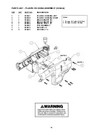
Page 13: ...3521 SIDEPLATE ASSY 7 1 005464 WASHER 8 1 423790 SHCS M6 x 25 9 1 423549 SHCS M6 x 18 10 1 400418 ROLLER SHAFT 11 1 800417 ROLLER 12 1 800416 SPRING 13 1 800412 RELEASE LEVER 14 2 800435 SHCS M3 x 5 15 1 800435 FRONT COVER 16 1 800447 MOTOR ASSEMBLY 17 1 800444 PLASTIC HOUSING ASSY 18 1 800396 MOTOR ADAPTER 19 2 800432 SHCS M4 x 12 20 1 800434 O RING 21 1 800413 KEY 22 1 800455 WAVE WASHER 23 1 80...

Page 14: ...IC HOUSING ASSEMBLY 800444 KEY QTY PART NO DESCRIPTION 1 1 800397 PLASTIC HOUSING LEFT 2 1 800398 PLASTIC HOUSING RIGHT 3 1 800424 BRASS INSERT M3 4 9 800423 BRASS INSERT M4 5 1 800426 DOWEL PIN 4 x 30 6 1 800395 PCB ASSEMBLY 7 1 800430 SHCS M3 x 8 8 9 800429 SHCS M4 x 16 14 ...

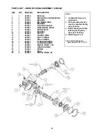
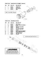
Page 15: ...O DESCRIPTION 1 1 008752 N5000 62 2 1 008751 NEEDLE ROLLER BEARING 3 1 008756 BEARING 4 1 800436 RETAINING RING 5 1 024038 BEARING 6 1 423533 THRUST WASHER 7 1 423501 FEED WHEEL SHAFT 8 1 800400 WORM GEAR 9 1 423515 BEARING 10 1 800448 COVER 11 1 250731 TRUARC RING 12 1 423531 SAE 18 ORING 13 1 256755 SAE 30 ORING 14 1 800120 FLANGE BEARING 15 1 800401 FLANGE BEARING 16 1 800438 DOWEL PIN M5 x 20 ...

Page 16: ...54 RING PARTS LIST GEARING 800453 KEY QTY PART NO DESCRIPTION 1 3 800256 RING GEAR 2 2 800251 IDLER CARRIER ASSEMBLY 3 12 800258 IDLER 4 2 800295 12mm BALL BEARING 5 1 800323 O RING 6 1 429266 10mm BALL BEARING 7 1 800318 5 8 X 7 8 X 020 SHIM 8 1 800324 O RING 9 1 800253 IDLER CARRIER ASSEMBLY 10 1 800403 DRIVE PINION ASSEMBLY 11 1 800407 GEAR END PLATE 12 1 800458 RETAINING RING 13 1 800457 SPACE...

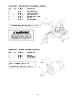
Page 17: ...ER FOOT ASSEMBLY 800445 KEY QTY PART NO DESCRIPTION 1 1 800410 BREAKER FOOT 2 1 252262 NOSE PIN i8 X 26 3 1 800602 BREAKER NOSE 4 1 423524 ROLLER PIN i10 X 50 5 1 423517 ROLLER 6 1 423546 NOSE SPRING PARTS LIST MOTOR ASSEMBLY 800447 KEY QTY PART NO DESCRIPTION 1 1 800422 MOTOR 2 1 800404 DRIVE SHAFT 3 1 800431 KCPSS M3 X 3 17 ...

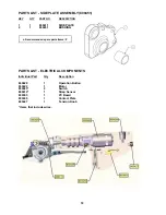
Page 18: ... DESCRIPTION 1 1 800411 SIDE PLATE 2 1 800451 BUSHING PARTS LIST ELECTRICAL COMPONENTS Individual Part Qty Description 800428 1 Operation Button 800422 1 Motor 800425 2 Switch 800414 1 Strap Sensor 800395 1 PC Board 800005 1 Contact Plate 800427 1 Tension Knob Items that include wires 18 ...

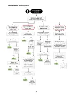
Page 19: ... Repair as needed Inspect and replace parts as needed Electrical Kit 800395 Operate Tool Does tool function YES PASS NO Contact authorized Signode repair center Operation Button does not light Remove battery and inspect connection terminals Terminals appear damaged YES Repair or replace battery Contact Plate 800005 NO Remove side covers and inspect the tool for broken wires Repair as needed Operat...

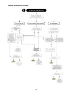
Page 20: ...T button on battery Does battery pass YES NO Battery possibly faulty or old Replace battery Operate Tool Does tool function YES NO Contact authorized Signode repair center Low strap tension Inspect the feedwheel operating condition Does the feedwheel appear to be packed with debris NO Does the feedwheel appear to be worn or is the feedwheel milling on the strapping YES Replace parts as needed Feed...

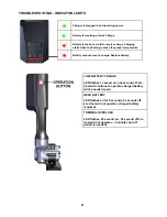
Page 21: ...perature Battery cannot accept a charge Replace battery LOW BATTERY CHARGE LED flashes 1 second on one second off etc tool will continue to operate charged battery will be needed soon DEAD BATTERY LED flashes on for 5 seconds 5 seconds off etc tool will not operator charged battery required THERMAL OVERLOAD LED flashes 25 second on 25 second off etc tool will not operator 5 minute cool off period ...

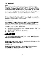
Page 22: ... instructions found in this manual SERVICE INTERVALS Tool component wear is affected by the environment strap seal quantity and strap gauge which the tool is subjected to All critical moving components of the tool should be inspected periodically Broken parts can increase sealing effort leading to additional component wear and produce lower joint strength Inspect the components of the sealing mech...

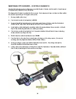
Page 23: ...r 4 Insert battery while holding the operation button for approximately three seconds LED will flash 1 time indicating the button is working correctly 5 Turn tension control knob pointer to 5 Operation Button LED will flash 5 times indicating tension knob is working correctly 6 Rotate tension control knob back to level MODE 7 Turn the tool on it s side Place a small piece of strap over the strap s...

Page 24: ...under the feedwheel Strap must be only under the feedwheel and NOT cover strap sensor 4 Insert battery while holding the operation button for approximately two seconds LED will flash 1 time indicating the button is working correctly 5 Wait 30 seconds 6 Cycle counter codes begin to be displayed as follows Example a tool that has run 1253 complete cycles 0 0 1 2 5 3 FIRST DIGIT SECOND DIGIT THIRD DI...

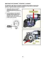
Page 25: ... routine tool maintenance procedures Adjust the feedwheel clearance as follows 1 Using a 2 5mm hex wrench turn the adjustment screw which can be accessed through the top of the tool as shown 2 Turn the adjustment screw clockwise for greater clearance and counter clockwise for less clearance Turn the adjustment screw only in 1 8 turn increments After each 1 8 turn test the tool from proper operatio...

Page 26: ...26 ...

Page 27: ...claration Date 1 March 2013 Machine Description Grippack Machine Type Battery Powered Hand Tool Provisions with which machinery complies 2006 42 EC 2006 95 EC 2004 108 EC Harmonized EuroNorms with which machinery complies EN 60734 1 2009 EN 60745 2 18 2009 EN ISO 12100 2010 EN 60204 1 2006 EN 13849 1 Technical Standards with which machine complies NA EC Authorized Representatives Tim Dunlavy G S L...

Page 28: ...EPRESENTATIVE C PURCHASER FOLLOWING THE SIGNODE PRESCRIBED MAINTENANCE SCHEDULE OPERATING AND OTHER INSTRUCTIONS FAILURE TO FOLLOW THE ABOVE EXPRESS CONDITIONS SHALL VOID ALL WARRANTIES OTHERWISE APPLICABLE TO THE PRODUCTS OR SERVICES SIGNODE EQUIPMENT AND TOOLS ARE DESIGNED MANUFACTURED AND TESTED USING SIGNODE MANUFACTURED STRAPPING SEALS AND PARTS USE OF NON SIGNODE MANUFACTURED STRAPPING AND S...

Reviews: